Display With An Electro-Optical Display Module

a technology of display module and display module, applied in the direction of optical elements, lighting and heating apparatus, instruments, etc., can solve the problems of achieve the effect of avoiding undesired gaps or joints

Active Publication Date: 2015-03-05
CONTINENTAL AUTOMOTIVE GMBH
View PDF2 Cites 1 Cited by
  • Summary
  • Abstract
  • Description
  • Claims
  • Application Information

AI Technical Summary

Benefits of technology

The invention provides displays with trim elements or information elements without any gaps or joints by using a transparent cover with a three-dimensional configuration. This allows for additional components to be mounted under the trim elements or scale rings, and also results in a uniform appearance when only the cover is bonded onto the display area. The cover can be produced easily and inexpensively as a film with a three-dimensional design implemented through deep-drawing or printing. The technical effects include improved design and more uniform appearance, as well as compatibility with various display technologies such as OLED, LCD, and LED.

Problems solved by technology

When trim elements or information elements, such as scale rings for example, are mounted on the cover, undesired gaps or joints occur.

Method used


Image

  • Display With An Electro-Optical Display Module
  • Display With An Electro-Optical Display Module
  • Display With An Electro-Optical Display Module

Examples


Embodiment Construction

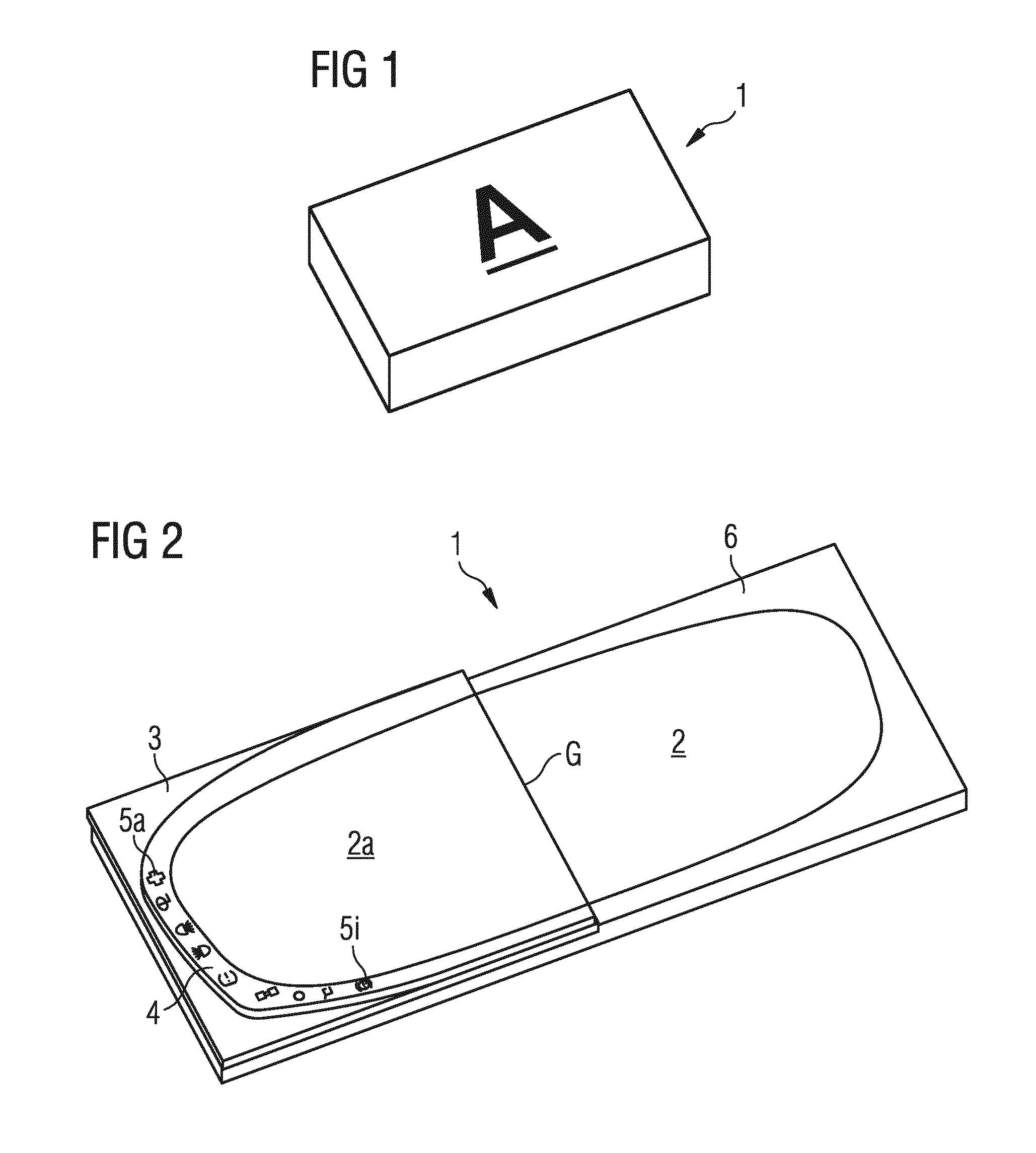
[0015]The electro-optical display module in FIG. 1 is configured, for example, as a liquid-crystal display and has a display area A which usually covers virtually a complete side of the display module. The display module can, for example, be configured as a point-matrix display; there are, however, also other possible electro-optical display modules.

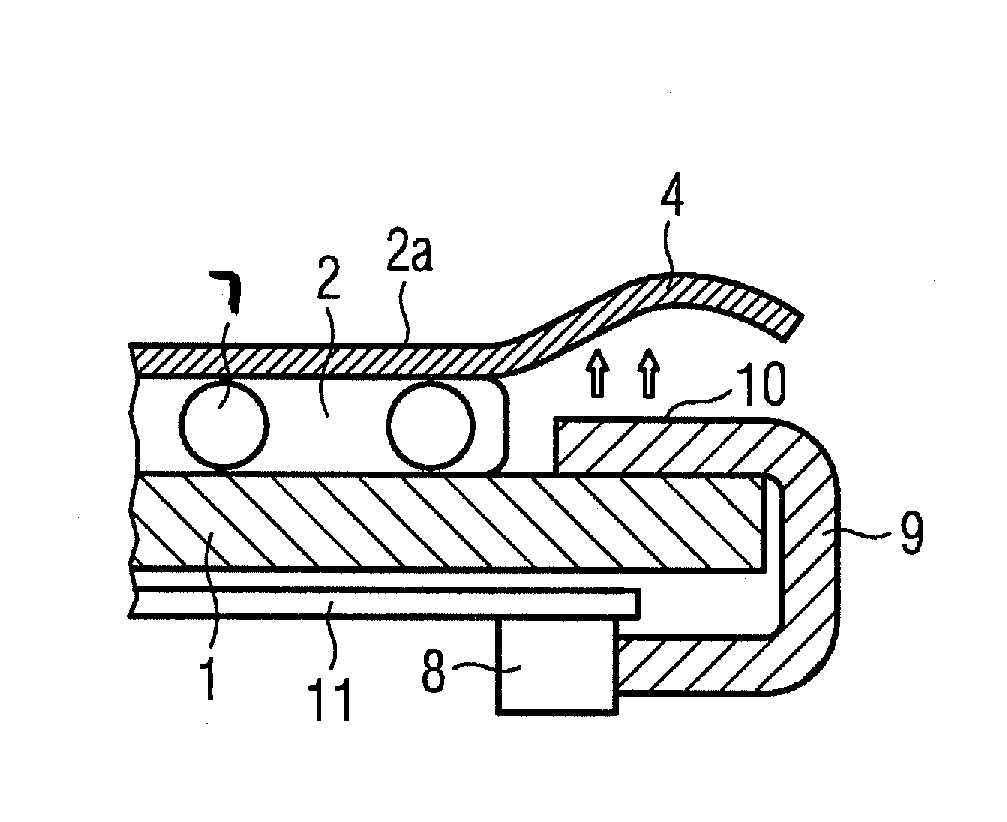
[0016]The first exemplary embodiment of the inventive display in FIG. 2 shows the electro-optical display module 1 having the display area A and shows a cover 3 of which only half is illustrated and which has a three-dimensional structure 4. Backlit symbols 5a to 5i are illustrated in the three-dimensional structure 4 configured as a trim frame. The symbols 5a to 5i can, for example, be implemented by printing the cover 3. The print can be configured thereby such that the symbols can be perceived only when they are appropriately backlit. This is possible, for example, by applying to the printed symbols in the direction of a possible obse...


PUM

PropertyMeasurementUnit
diameteraaaaaaaaaa
transparentaaaaaaaaaa
refractive indexaaaaaaaaaa

Abstract

A display with an electro-optical display module has a display area, with a light-transmissive cover arranged between the display area and a possible observer of the display area. The light-transmissive cover is bonded onto the display area by an adhesive, and provision is made for the surface of the light-transmission cover to be configured in a three-dimensional fashion.

Description

CROSS REFERENCE TO RELATED APPLICATIONS[0001]This is a U.S. national stage of application No. PCT / EP2012 / 076056, filed on Dec. 19, 2012. Priority is claimed on German Application No. DE102011089266.4, filed Dec. 20, 2011, the content of which is incorporated herein by reference.BACKGROUND OF THE INVENTION[0002]1. Field of the Invention[0003]The invention relates to a display with an electro-optical display module, having a display area and a transparent cover arranged between the display area and a possible observer of the display area, the transparent cover being bonded onto the display area by a transparent adhesive.[0004]2. Description of Prior Art[0005]Electro-optical display modules are, for example, liquid-crystal displays or organic light-emitting diodes displays used, for example, as displays or combined display and input areas, for example in cell phones. In order to protect electro-optical display modules, they are additionally covered with transparent covers bonded onto t...

Claims


Application Information

Patent Timeline
Patent Type & Authority Applications(United States)
IPC IPC(8): G02F1/1335G02F1/1339G02F1/1333
CPCG02F1/133524G02F2202/28G02F1/13392G02F1/1333G02F1/133308G02F1/133311G02F1/133331
Inventor MARQUARDT, HELMUTPAWUSCH, WOLFGANG-PETERWEDEL, HANS
Owner CONTINENTAL AUTOMOTIVE GMBH
Why Eureka
Try Eureka