Cap with an openable lid

a technology of openable lids and caps, which is applied in the direction of lids/covers, packaging, non-removable lids/covers, etc., can solve the problems of difficulty in discharging container contents, cap is easily lost and/or forgotten, and cannot discharge container contents, etc., to achieve smooth rotation up and down and smooth movement

Active Publication Date: 2015-03-05
HIRO PLUS ATA HIRO PLUS
View PDF6 Cites 4 Cited by
  • Summary
  • Abstract
  • Description
  • Claims
  • Application Information

AI Technical Summary

Benefits of technology

[0030]On cap with an openable lid of the present invention, since radius of rotation of the hinge provided at a predetermined position is smaller than radius of rotation of the pushing portion, it is possible that the lid rotates when reactive force against force added on pushing portion reaches from hinge to the lid. Further, push button is pushed in connection with opening of the lid since the pushing portion is provided at the position where the pushing portion reaches top edge of the push button at the lid being opened. Thereby, it is possible to realize a structure of discharging contents of container by pushing push button without removing cap.
[0031]The push button may be fixed at a desired direction since side wall of outside of the push button is respectively abutted to corresponding inner wall of cap body when the cap is mounted on a container. Thereby, structure of always discharging contents of container at a desired direction can be practiced.
[0032]The push button is fixed at a desired direction without rotating thereof since cross-section shape of the push button is non-circler shape and button holder is adapted to at least in a circumferential shape of the bush button. Further, the button holder smoothly rotates up and down in connection with motion of the pushed push button since the button holder is connected with the end of cap body through a plate member provided toward the same direction as the direction of the opening of the lid. Thereby, it is possible to realize a structure of discharging contents of container at a desired direction at the push button being pushed.
[0033]It is possible to realize a structure of always discharging contents of container at a desired direction without coming away or declination of the button holder against motion of push button since the button holder is formed as cap shape adjusted to the rectangular push button, and side surface of the button holder is provided with an aperture at the position of opening the discharge hole of the push button.
[0034]Since the push button is integrally formed with the cap body, and the push button is connected to the end of the cap body through the plate member provided in the same direction as the opening of the lid, it is possible that the push button smoothly moves in connection with movement of the pushed pushing portion. This makes it possible to realize a structure of integrally producing the cap and the push button at a production process.
[0035]Since a drip off prevention provided on rear surface of the lid is placed at the position adjacent to the discharge hole of nozzle at the lid being closed, it is possible to prevent remaining liquid at front edge of the nozzle being blocked at the drip off prevention and dripping off of the liquid. This makes situation of that the drip off prevention blocks the discharge hole of the nozzle.

Problems solved by technology

It is not possible to discharge contents of the container by means of the above described cap unless the container is inclined.
On spray-type containers, cap for protecting push button is mounted in the aspects of health and safety, but such cap is to be removed from container for use each time, and such cap is easily lost and / or forgotten to be mounted on the container.
Thereby opening of container may be unclean by dirt or dust, and it causes difficulty of discharging contents of container.

Method used


Image

  • Cap with an openable lid
  • Cap with an openable lid
  • Cap with an openable lid

Examples


Embodiment Construction

)

[0044]In describing the preferred embodiment of the present invention, reference will be made herein to FIG. 1—of the drawings in which like numerals refer to like features of the invention.

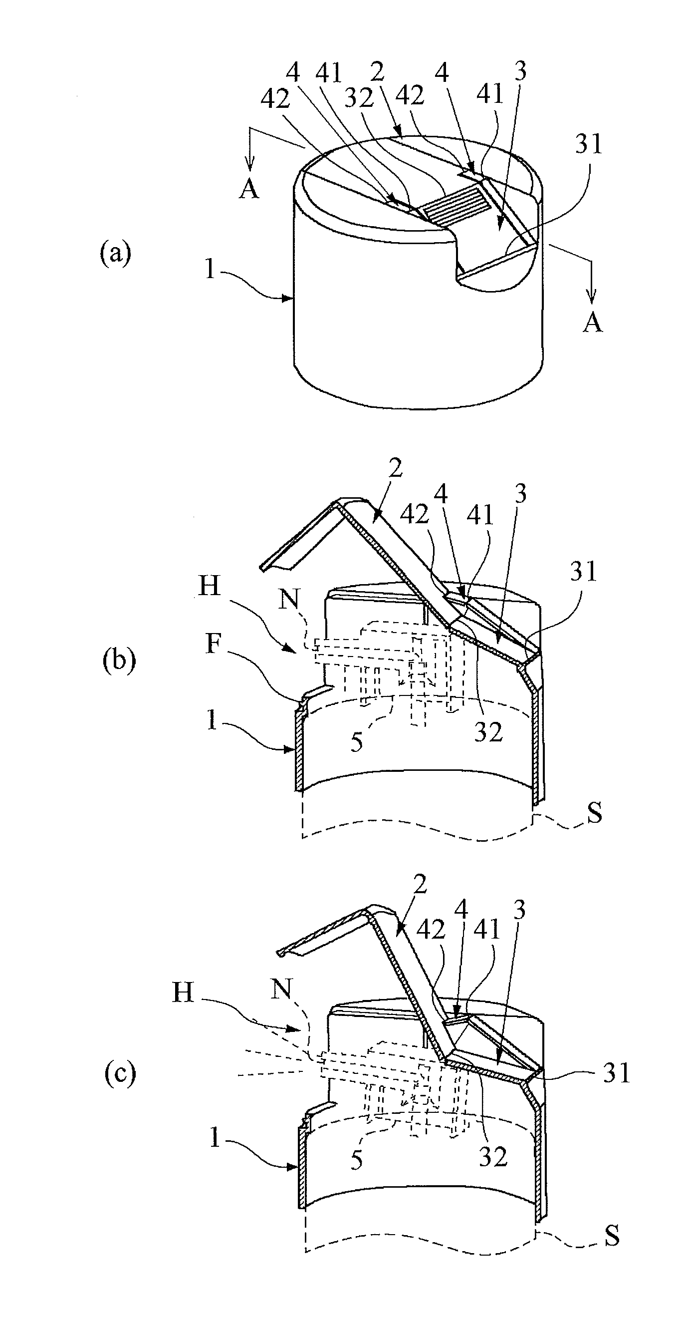
[0045]FIG. 1 shows basic structure of a cap with an openable lid in accordance with the present invention. FIG. 1 (a) is an outline view of a cap with an openable lid, FIGS. 1 (b) and (c) are cross-section views where the cap with an openable lid is used instead of usual caps. Assumed push button is described by dot-lines.

[0046]As shown in the FIGS. 1 (a) and (b), the cap with an openable lid comprises a cap body 1, which is cylindrical, hollow, and being mounted on a container S, for covering a push button 5 including a discharge hole N, and a L-shape lid 2 partially forming top surface and side surface of the cap body 1. The lid 2 is connected to the cap body 1 through a plate-shaped pushing portion 3 and a hinge 4. The portion where the pushing portion 3 and the cap body 1 are connected is a ...


PUM


Abstract

Containers are to be mounted with cap having structure usable without removing the cap. Cap with an openable lid of the present invention is that lid is rotated when reactive force against force added on pushing portion 3 reaches from hinge 4 to the lid 2 since radius of rotation of the hinge 4 provided at a predetermined position is smaller than radius of rotation of the pushing portion 3. Further, push button 5 is pushed in connection with opening of the lid since the pushing portion 3 is provided at the position where the pushing portion is adjacent to top edge of the push button 5 at the lid 2 being opened by the hinge 4. Thus, the force reaches the push button 5 through the pushing portion 3, and backward of the push button inclines. This makes it possible to realize a structure of discharging contents of container without removing cap.

Description

BACKGROUND OF THE INVENTION[0001]1. Field of the Invention[0002]Subject invention relates to a cap with an openable lid mounted on a container for discharging contents thereof by pushing a push button, and more particularly relates to a cap with an openable lid for discharging contents of a container by opening a lid constructing a part of the cap and the push button being pushed thereby.[0003]2. Description of Related Art[0004]Caps covering opening of container containing contents are well known, and cap by structure of mounting a lid to cap body through a hinge and exposing an opening by opening the lid is a type of such caps. This type of caps are not lost or forgotten to be on containers because the cap body is mounted to the container. However, it takes time and may be troublesome to disengage a lid from a hook of the cap body due to some required actions therefor, for example, flipping lid by fingers, pushing up lid by a hand while holding the container by the another hand, et...

Claims


Application Information

Patent Timeline
Patent Type & Authority Applications(United States)
IPC IPC(8): B65D47/20
CPCB65D47/2018B65D83/206B65D83/40B65D83/753B65D83/16
Inventor ITO, HIROSHI
Owner HIRO PLUS ATA HIRO PLUS
Why Eureka
Try Eureka