
Conductive structure and manufacturing method thereof

a manufacturing method and conductive technology, applied in the direction of superimposed coating process, liquid/solution decomposition chemical coating, resistive material coating, etc., can solve the problem of relatively high manufacturing cost of transparent conductive sheets, and achieve the effect of less raw material cost, reduced junction resistance and high transparency

Inactive Publication Date: 2015-03-05
NATIONAL TSING HUA UNIVERSITY
View PDF12 Cites 3 Cited by
  • Summary
  • Abstract
  • Description
  • Claims
  • Application Information

AI Technical Summary

Benefits of technology

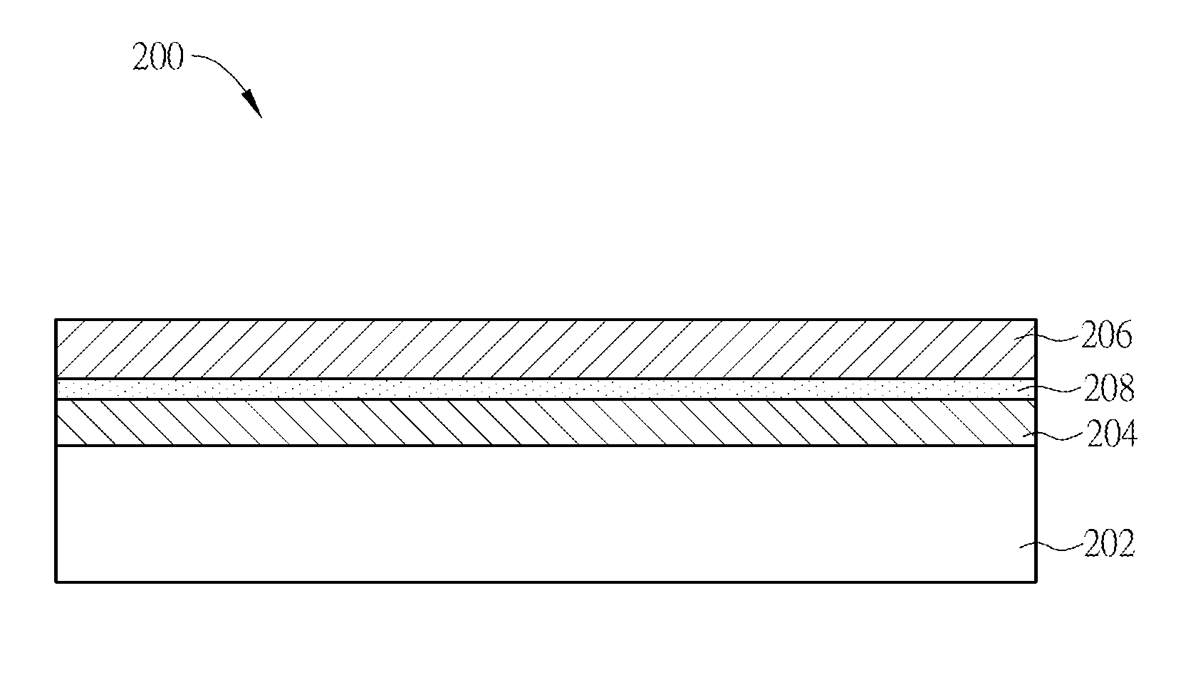
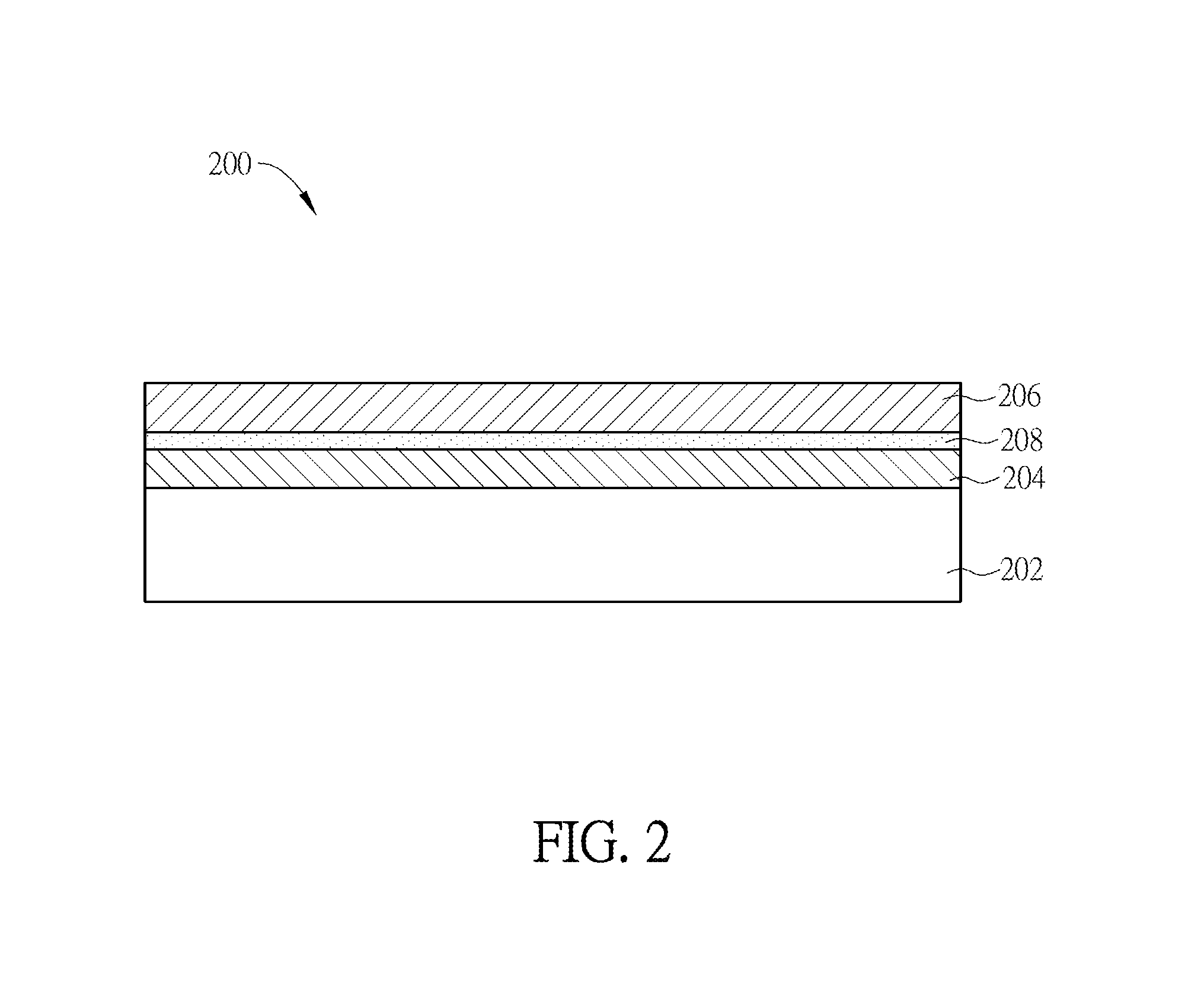
The invention is about a new way to make a conductive structure by coating a suspension solution with a blade or bar along a specific direction and at a set speed. This results in most of the nanowires in the suspension solution aligning in the same direction. By forming two coatings at different directions on a single substrate, the manufactured conductive structure contains overlapping nanowires in two directions. This configuration has several benefits, including higher transparency, less raw material costs, and improved conductivity. Adding conductive materials to the structure also reduces resistance between the nanowires.

Problems solved by technology

However, the vacuum sputtering equipment for ITO coating process is very expansive, so the manufacturing cost for the transparent conductive sheet is relatively higher.

Method used


Image

  • Conductive structure and manufacturing method thereof
  • Conductive structure and manufacturing method thereof
  • Conductive structure and manufacturing method thereof

Examples


Embodiment Construction

[0030]The present invention will be apparent from the following detailed description, which proceeds with reference to the accompanying drawings, wherein the same references relate to the same elements.

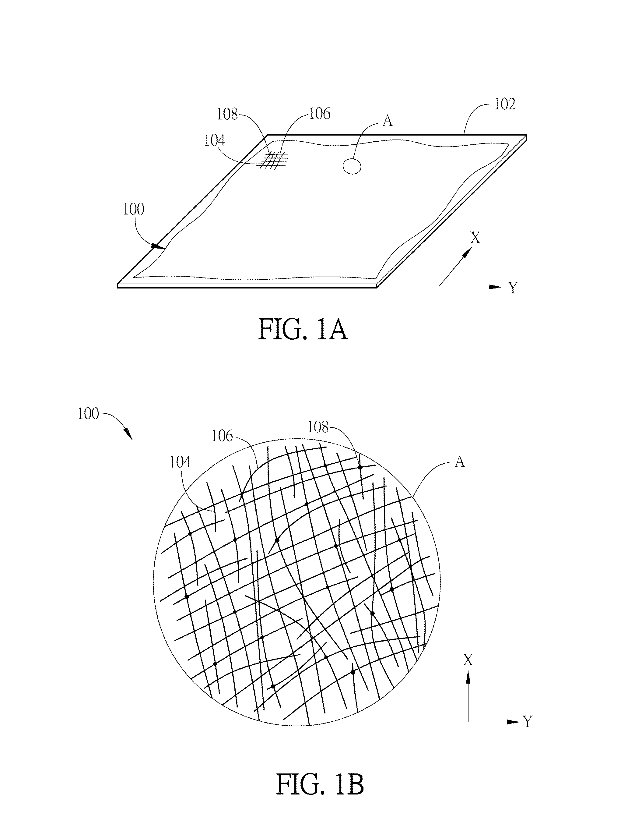
[0031]FIG. 1A is a schematic diagram showing a conductive structure 100 according to an embodiment of the invention, and FIG. 1B is an enlarged view of the area A of the conductive structure 100 as shown in FIG. 1A. Referring to FIGS. 1A and 1B, the conductive structure 100 is formed on a substrate 102 and includes a plurality of first nanowires 104 and a plurality of second nanowires 106. The first nanowires 104 extend along a first direction (e.g. the X direction) substantially. The second nanowires 106 extend along a second direction (e.g. the Y direction) substantially. A part of the first nanowires 104 and the second nanowires 106 are overlapped and contacted to form electrical connections. Since the first nanowires 104 and the second nanowires 106 are substantially disposed alon...


PUM

PropertyMeasurementUnit
speedaaaaaaaaaa
speedaaaaaaaaaa
included angleaaaaaaaaaa

Abstract

A conductive structure comprises a plurality of first nanowires and a plurality of second nanowires. The first nanowires extend along a first direction substantially. The second nanowires extend along a second direction substantially, and at least a part of the second nanowires electrical connect to the first nanowires. The included angle between the first and second directions is nonzero. A manufacturing method of the conductive structure is also disclosed.

Description

CROSS REFERENCE TO RELATED APPLICATIONS[0001]This Non-provisional application claims priority under 35 U.S.C. §119(a) on Patent Application No(s). 102131901 filed in Taiwan, Republic of China on Sep. 4, 2013, the entire contents of which are hereby incorporated by reference.BACKGROUND OF THE INVENTION[0002]1. Field of Invention[0003]The present invention relates to a conductive structure and a manufacturing method thereof, and particularly to a transparent conductive nano-structure and a manufacturing method thereof.[0004]2. Related Art[0005]The common transparent conductive sheet is a conductive and light permeable coating or film, and it has been widely adopted in many applications such as displays, touch panels, solar cells, and other photoelectrical devices. In general, the transparent conductive sheet is mainly made of ITO. However, the vacuum sputtering equipment for ITO coating process is very expansive, so the manufacturing cost for the transparent conductive sheet is relati...

Claims


Application Information

Patent Timeline
Patent Type & Authority Applications(United States)
IPC IPC(8): H05K1/09H05K3/46H05K1/02
CPCH05K1/097H05K1/0274H05K2201/0302H05K2201/0326H05K3/4664H05K3/12H05K3/1283H05K2201/026H05K2201/10128
Inventor LIN, HAO-WUCHIANG, KAI-MINGCHANG, JUNG-HAOHUANG, CHENG-YULU, CHIH-WEI
Owner NATIONAL TSING HUA UNIVERSITY
Learn More