
System and method for controlling fuel distributions in a combustor in a gas turbine engine

a technology of gas turbine engine and fuel distribution, which is applied in the field can solve the problems of difficult to maintain low emissions, undesirable emissions of gas turbine engines, and difficult to achieve low emissions

Inactive Publication Date: 2015-03-05
GENERAL ELECTRIC CO
View PDF9 Cites 31 Cited by
  • Summary
  • Abstract
  • Description
  • Claims
  • Application Information

AI Technical Summary

Benefits of technology

This patent describes a method of operating a gas turbine engine that involves directing fuel to multiple combustors using a controller. Each combustor has a fuel nozzle and a fuel injector positioned at either end. The method also includes stopping the flow of fuel to one group of combustors and adjusting the flow of fuel to another group using the controller. The technical effect is a more efficient and precise control of fuel delivery to multiple combustors, which can improve engine performance and efficiency.

Problems solved by technology

Some gas turbine engines produce undesirable emissions, such as oxides of nitrogen (NOx), unburned hydrocarbons (HC), and carbon monoxide (CO).
However, when operating at reduced rates, it is difficult to maintain low levels of emissions.
For example, the temperature within the combustor may be too low to completely combust fuel when the gas turbine engine is operating at a reduced rate, and as a result, the gas turbine engine may produce undesirable emissions.

Method used


Image

  • System and method for controlling fuel distributions in a combustor in a gas turbine engine
  • System and method for controlling fuel distributions in a combustor in a gas turbine engine
  • System and method for controlling fuel distributions in a combustor in a gas turbine engine

Examples


Embodiment Construction

[0015]One or more specific embodiments of the present invention will be described below. In an effort to provide a concise description of these embodiments, all features of an actual implementation may not be described in the specification. It should be appreciated that in the development of any such actual implementation, as in any engineering or design project, numerous implementation-specific decisions must be made to achieve the developers' specific goals, such as compliance with system-related and business-related constraints, which may vary from one implementation to another. Moreover, it should be appreciated that such a development effort might be complex and time consuming, but would nevertheless be a routine undertaking of design, fabrication, and manufacture for those of ordinary skill having the benefit of this disclosure.

[0016]When introducing elements of various embodiments of the present invention, the articles “a,”“an,”“the,” and “said” are intended to mean that ther...


PUM


Abstract

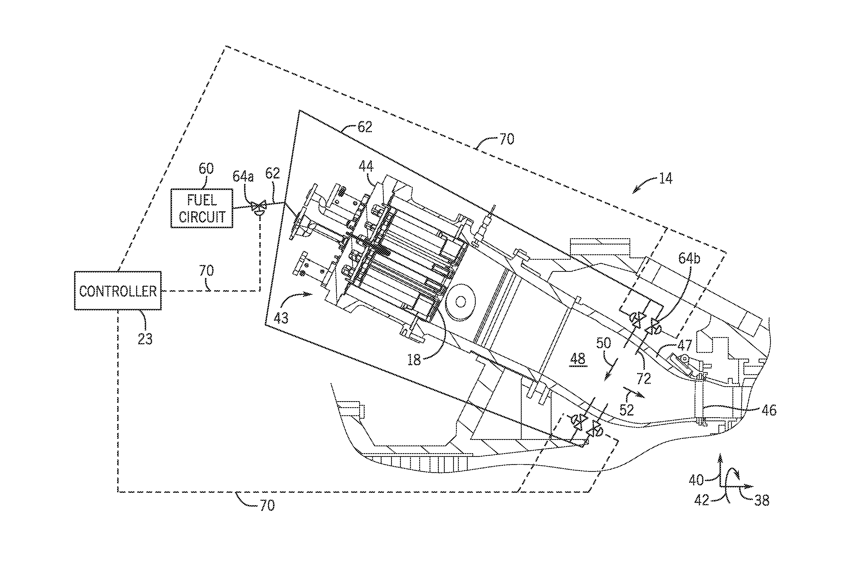
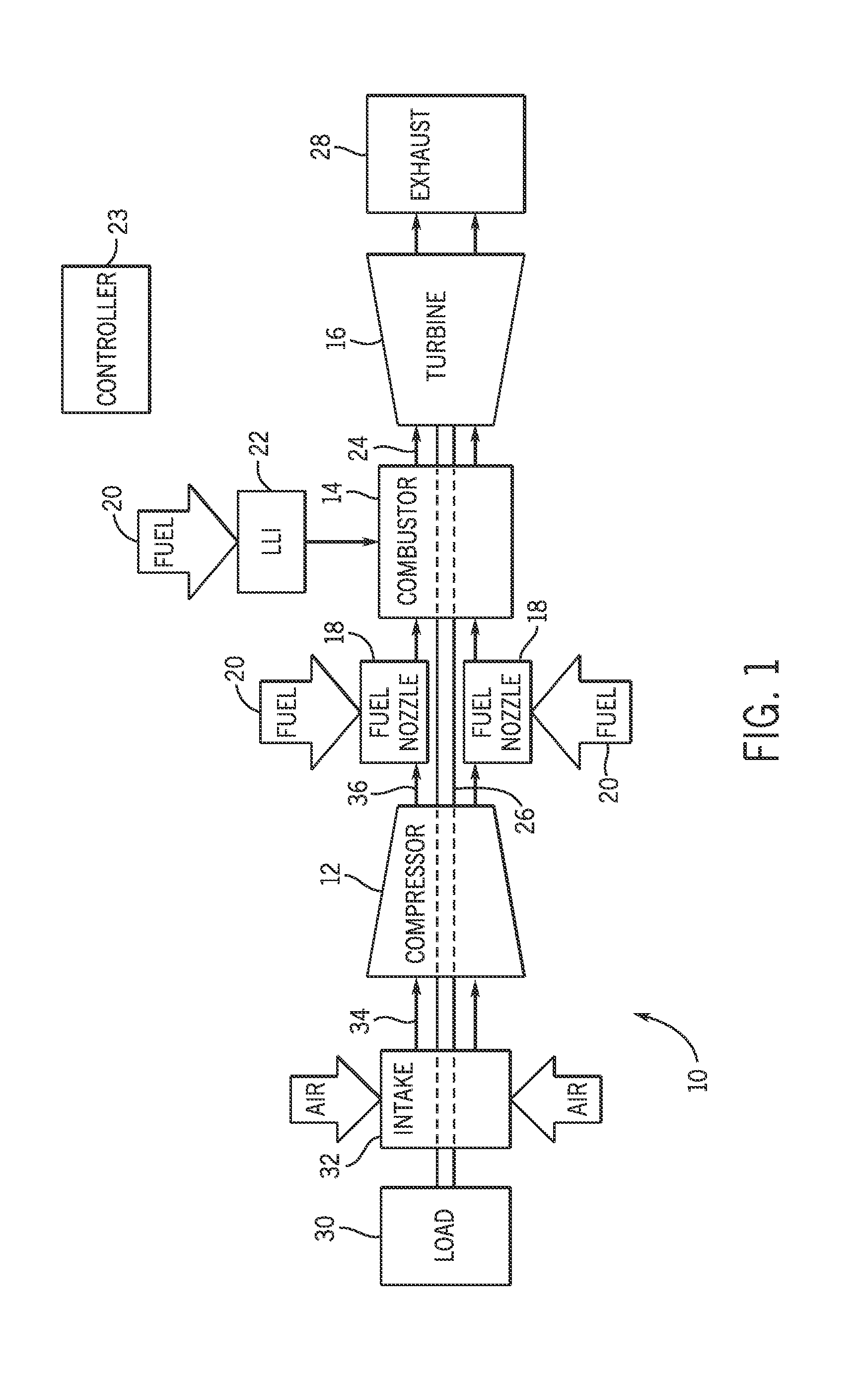
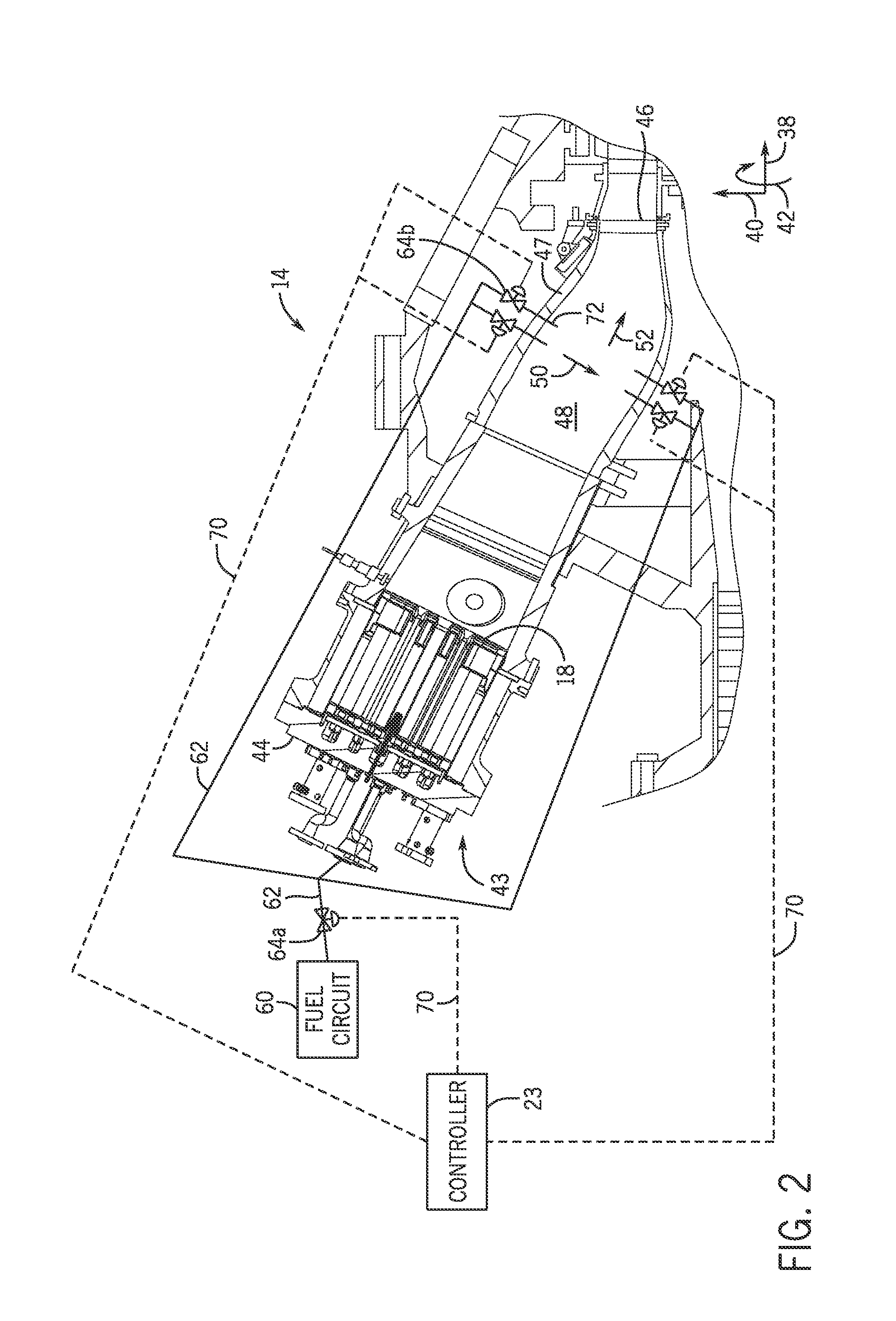
The present disclosure relates to a gas turbine engine system having a plurality of combustors, wherein a first combustor includes one or more fuel nozzles and one or more fuel injectors positioned downstream from the fuel nozzles. The gas turbine engine may also include a first valve disposed along a fuel delivery line between a fuel circuit and the first combustor to adjust a first flow of the fuel to the first combustor. The gas turbine engine may also include a second valve disposed along a fuel delivery line between the first valve and at least one of the one or more fuel injectors to adjust a second flow of the fuel to at least one of the one or more fuel injectors.

Description

BACKGROUND[0001]The subject matter disclosed herein relates generally to gas turbines, and, more particularly to systems and methods for operating gas turbines.[0002]Gas turbine engines include one or more combustors, which receive and combust air and fuel to produce hot combustion gases. Some gas turbine engines produce undesirable emissions, such as oxides of nitrogen (NOx), unburned hydrocarbons (HC), and carbon monoxide (CO). In some circumstances, it may be desirable to operate the gas turbine engine at a reduced rate or power level. However, when operating at reduced rates, it is difficult to maintain low levels of emissions. For example, the temperature within the combustor may be too low to completely combust fuel when the gas turbine engine is operating at a reduced rate, and as a result, the gas turbine engine may produce undesirable emissions.BRIEF DESCRIPTION[0003]Certain embodiments commensurate in scope with the originally claimed invention are summarized below. These ...

Claims


Application Information

Patent Timeline
Patent Type & Authority Applications(United States)
IPC IPC(8): F02C5/12G05D7/06
CPCG05D7/0617F02C5/12F02C7/228F02C7/232F05D2270/082F05D2270/083F23R3/346F23N2237/02F23N2241/20Y02T50/60
Inventor TORONTO, DAVID KAYLORCHEN, WEI
Owner GENERAL ELECTRIC CO
Learn More