Axial flow machine cooling system

a technology of axial flow and cooling system, which is applied in the direction of machines/engines, efficient propulsion technologies, stators, etc., can solve the problems of both the detriment and the impact of engine components, and achieve the effect of reducing the thermal load thereon

Active Publication Date: 2015-02-19
ROLLS ROYCE PLC
View PDF11 Cites 22 Cited by
  • Summary
  • Abstract
  • Description
  • Claims
  • Application Information

AI Technical Summary

Benefits of technology

The patent describes a cooling system for a turbine. The system has two inlets that supply air to the turbine. The first inlet cools the outer wall of the turbine by directing air in a reverse flow through an internal wall. The second inlet has a smaller height and is positioned in a way that airflow from this inlet does not recirculate and cause further heating. The two flows meet at a discontinuity and coalesce in a forward flow, which is parallel to the first inlet and cooler than the second inlet. This system effectively removes heat from the turbine and reduces thermal loading.

Problems solved by technology

The air which is extracted from the boundary layer has a higher temperature than the main gas path of the high pressure compressor, and this can have a detrimental impact on engine components both in the cavity, and in the high pressure turbine.

Method used


Image

  • Axial flow machine cooling system
  • Axial flow machine cooling system
  • Axial flow machine cooling system

Examples


Embodiment Construction

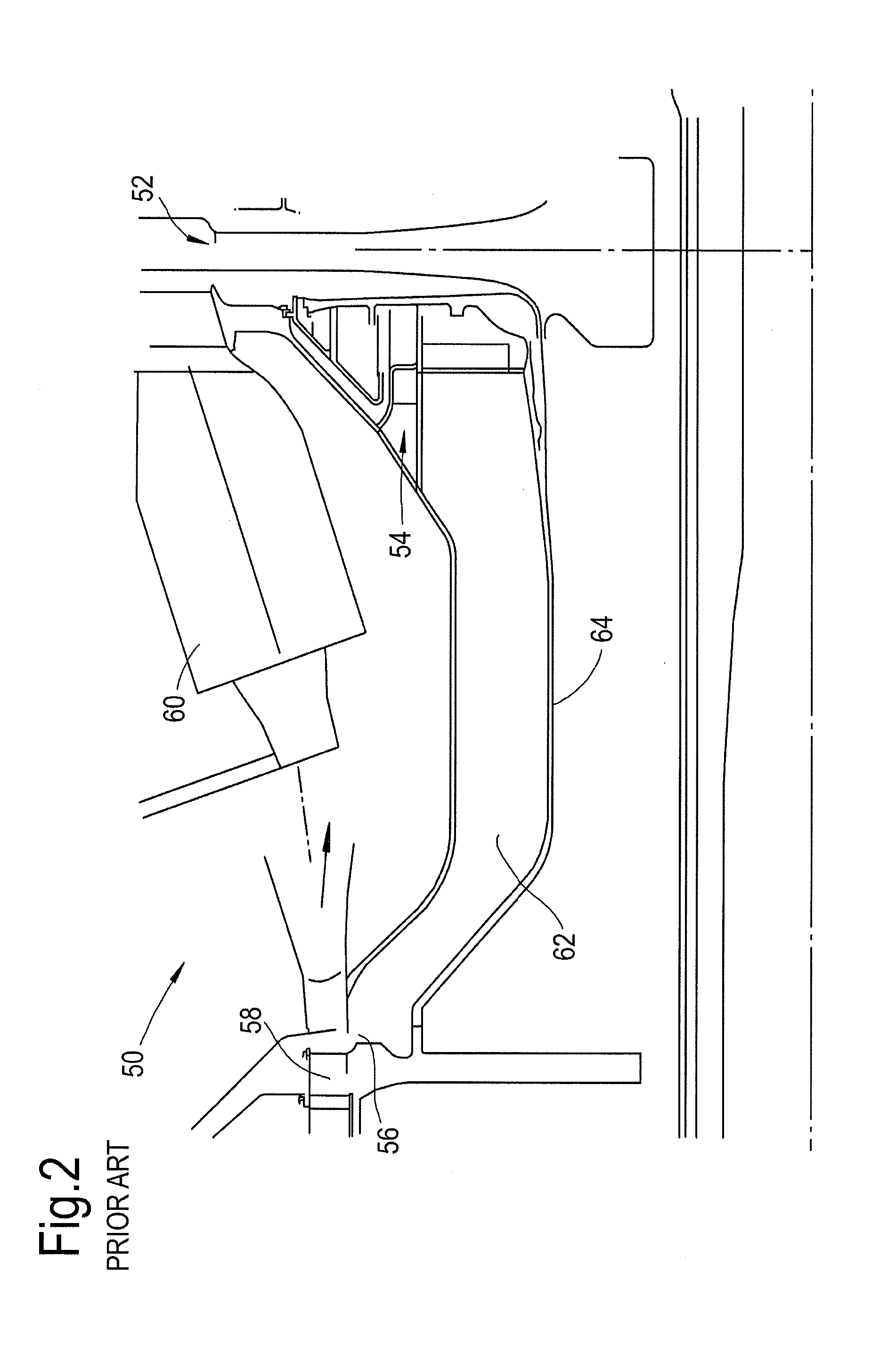
[0043]Referring to FIG. 2, there is shown a ventilation cavity system, generally designated 50, according to the prior art. In such a system 50, airflow from the compressor enters turbine 52 cooling flow ducting from first 54 and second 56 inlets. The first inlet 54 is fed by the primary flow of gas produced by the compressor 58. Such an airflow has been diffused as it is passed from the compressor into the larger volume surrounding the combustor 60, prior to entering the inlet 54 to provide a first cooling stream of air for the components of the turbine 52.

[0044]The airflow from the second inlet 56 is typically drawn from a boundary layer of the airflow through the compressor and enters the ventilation cavity 62. Such an airflow from the boundary layer is at a higher temperature than the temperature of the primary airflow through the compressor.

[0045]The airflow from the second inlet 56 passes along the shaft 64 connecting the high pressure compressor 58 to the high pressure turbin...


PUM


Abstract

This invention concerns a system for cooling components in a gas turbine engine, the gas turbine engine including a compressor for driving a primary gas flow to a combustor and a turbine arranged to be driven by combustion gases from the combustor, wherein the system includes: an annular cooling flow passage arranged for fluid communication between the compressor and the turbine, the flow passage having a first inlet arranged to receive gas from the primary gas flow downstream of compressor, and a second inlet located upstream of the first inlet, wherein the annular cooling flow passage has at least one internal wall for guiding airflow from the first inlet towards the airflow from the second inlet, the airflow from the first and second inlets coalesce within the annular flow passage prior to passing along the passage in a direction from the compressor to the turbine.

Description

[0001]This invention claims the benefit of UK Patent Application No. 1314773.1, filed on 19 Aug. 2013, which is hereby incorporated herein in its entirety.BACKGROUND OF THE INVENTION[0002]The present invention relates to the field of axial flow machine cooling or ventilation systems, and, more particularly, although not exclusively, to the field of gas turbine engine component cooling.[0003]With reference to FIG. 1, a ducted fan gas turbine engine according to the prior art generally indicated at 10 has a principal and rotational axis 11. The engine 10 comprises, in axial flow series, an air intake 12, a propulsive fan 13, an intermediate pressure compressor 14, a high-pressure compressor 15, combustion equipment 16, a high-pressure turbine 17, and intermediate pressure turbine 18, a low-pressure turbine 19 and a core engine exhaust nozzle 20. A nacelle 21 generally surrounds the engine 10 and defines the intake 12, a bypass duct 22 and a bypass exhaust nozzle 23.[0004]The gas turbi...

Claims


Application Information

Patent Timeline
Patent Type & Authority Applications(United States)
IPC IPC(8): F02C7/18F02C3/00
CPCF02C7/18F05D2260/20F05D2220/32F02C3/00F02C7/12F01D5/081F01D25/12Y02T50/60F01D25/08F01D5/082F01D5/08F02C6/08F01D5/046F01D9/06F05D2260/205
Inventor MAGUIRE, ALAN ROBERTSCANLON, TIMOTHY JOHNYOUNG, COLIN
Owner ROLLS ROYCE PLC
Why Eureka
Try Eureka