Thermal imaging device and thermal image photographing method

Active Publication Date: 2015-02-12
MISSION INFRARED ELECTRO OPTICS TECH
View PDF6 Cites 3 Cited by
  • Summary
  • Abstract
  • Description
  • Claims
  • Application Information

AI Technical Summary

Benefits of technology

This invention is a thermal imaging device and method that allows a user to capture images of objects using infrared technology. The device includes a reference image with specific position and dimensions that helps the user identify and photograph the object. The reference image serves as a visual prompt for the expected size and shape of the thermal image, which improves photographing quality and reduces technical requirements. The device is easy to use, produces high-quality images, and is useful for various applications such as analysis and record keeping.

Problems solved by technology

Thus, at present, if the detection quality needs to be ensured, the users need to think at the same time of photographing, thereby slowing a photographing speed.
If the speed is accelerated, a key photographing part or defects of the photographed object may be missed, affecting a state assessment effect.
Further, the users adjust a photographing position and dimension of a photographed object by subjective experience, causing thermal images of the same or similar photographed objects to exist differences in an imaging position, an imaging dimension, or an imaging angle each time, and missing the key photographing part.
Further, because of the differences, discreteness of data is difficult to control and analyze, and availability of vertical and horizontal analysis and comparison of the data is lower.
In addition, the thermal imaging data acquired according to the above may be difficult for subsequent batch processing of a computer.
However, the above method does not solve the problem.
According to the thermal imaging device in the prior art, even if the users learn a great deal of infrared photographing theory and knowledge of photographed objects, in the infrared detection, lacking effective means, the users still need to depend on subjective experience to select the photographing part, photographing angle, and photographing distance of the photographed object during photographing, with the lower photographing speed, large workload, and omissions.
In addition, since the requirements of the photographing region, angle, and distance are difficult to express, the higher level is hard to assign clear and definite detection quality requirements to the lower level.

Method used


Image

  • Thermal imaging device and thermal image photographing method
  • Thermal imaging device and thermal image photographing method
  • Thermal imaging device and thermal image photographing method

Examples


first embodiment

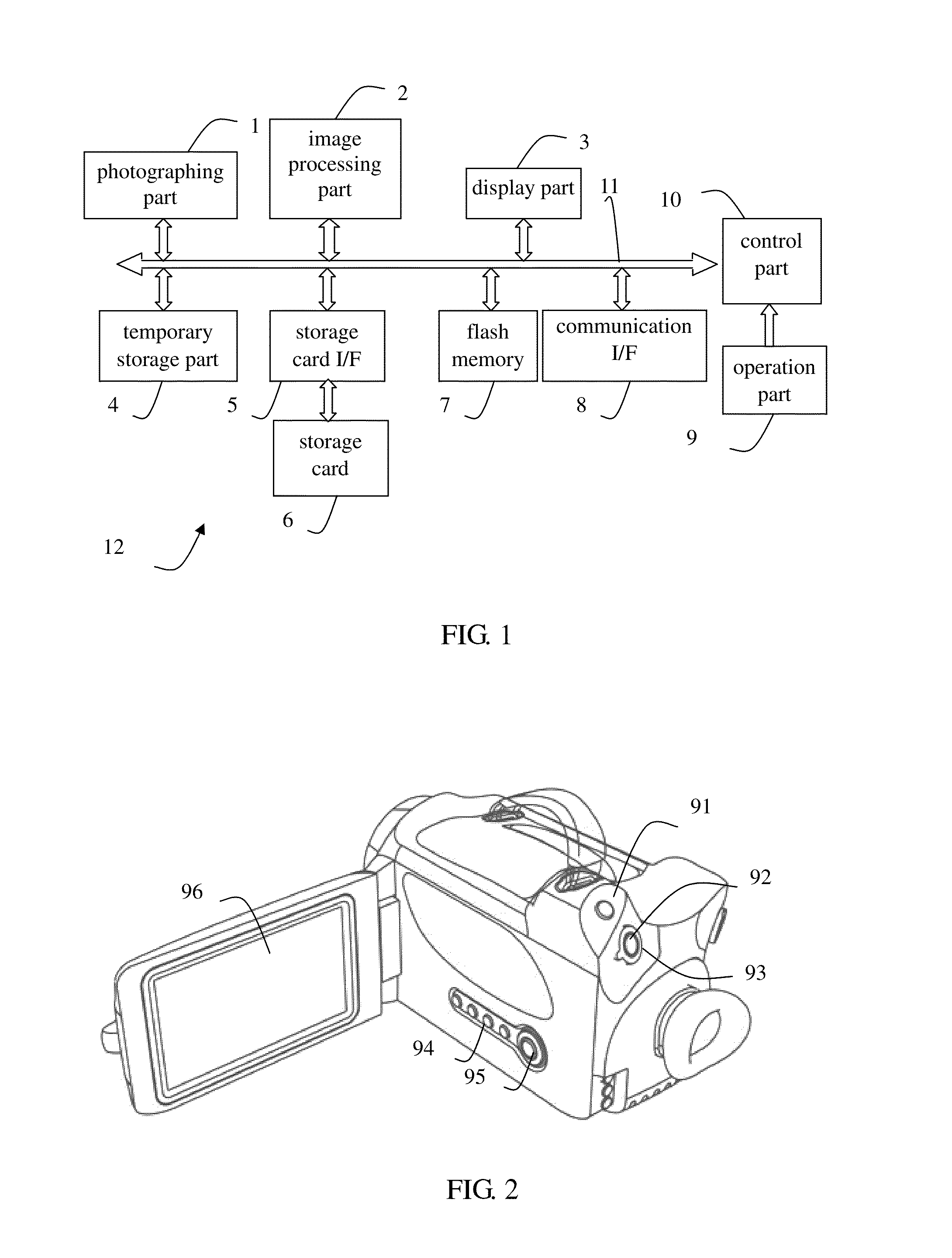
[0055]The first embodiment is described in detail according to FIG. 1. FIG. 1 is a block diagram showing a thermal imaging device 12 in the embodiments. FIG. 2 is an outline diagram showing the thermal imaging device 12 in the embodiments.

[0056]The thermal imaging device 12 includes a photographing part 1, an image processing part 2, a display part 3, a temporary storage part 4, a storage card I / F 5, a storage card 6, a flash memory 7, a communication I / F 8, an operation part 9, and a control part 10. The control part 10 is connected with each other part via a control and data bus 11, and is responsible for overall control of the thermal imaging device 12. The control part 10 may be realized by a CPU, a MPU, a SOC, or a programmable FPGA.

[0057]The photographing part 1 includes an optical part, a driving part, an infrared detector, and a signal preprocessing circuit, which are not shown. The optical part is composed of infrared optical lenses, and is used for focusing received infrar...

second embodiment

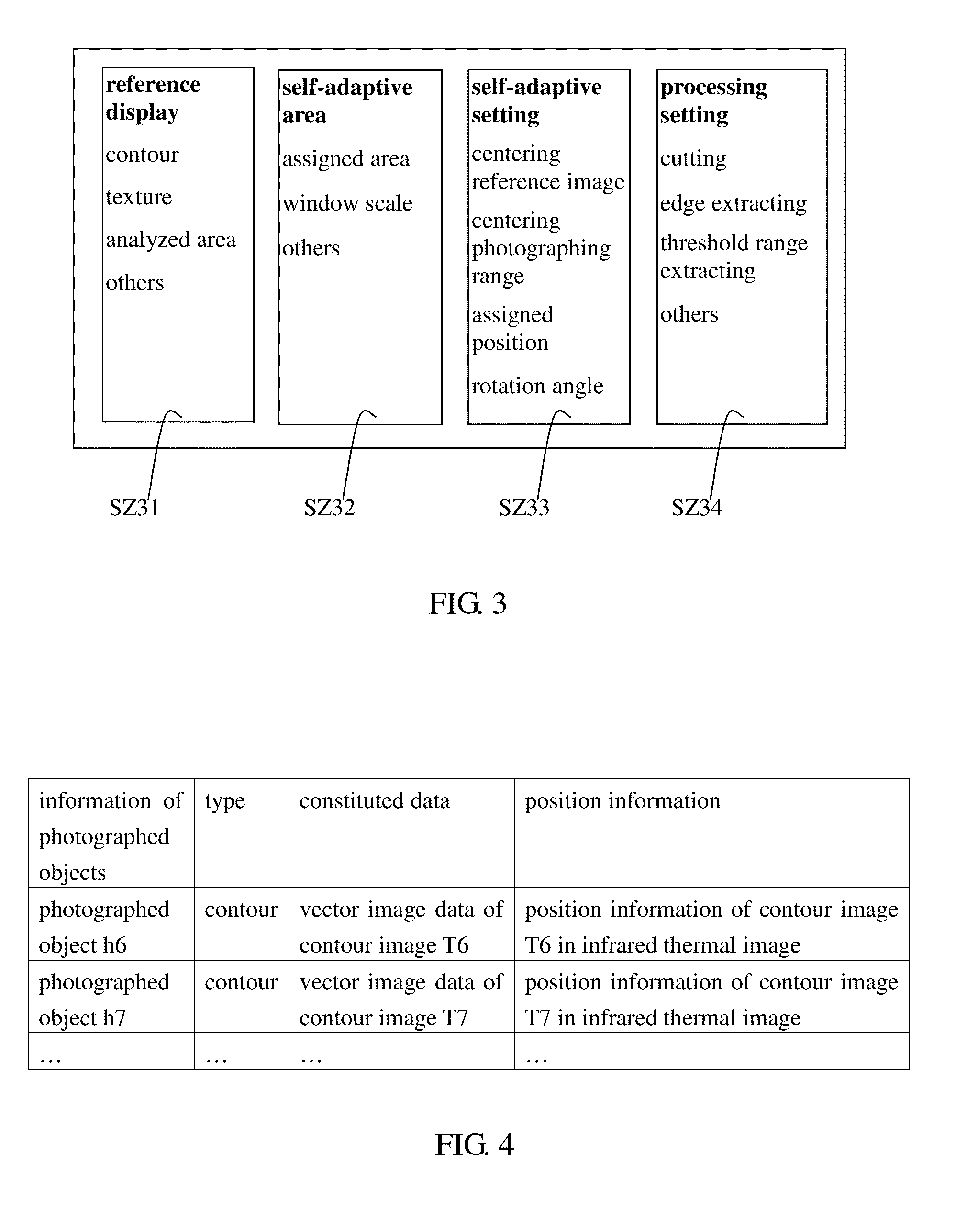
[0098]The control part 10 determines the specified position and the specified dimension of the contour image T7 located in the infrared thermal image according to the position information transmitted to the temporary storage part 4. For example, in FIG. 4, the flash memory 7 stores the morphological constituted data and the position information thereof. The position information represents the specified position and the specified dimension of the reference image generated by the morphological constituted data and located in the infrared thermal image, and the position determining part is used for determining the specified position and the specified dimension represented by the position information as the specified position and the specified dimension of the reference image acquired by the morphological constituted data in the infrared thermal image. In addition, the position, dimension, or rotating angles of the reference image may be determined via input of the user through the oper...

fourth embodiment

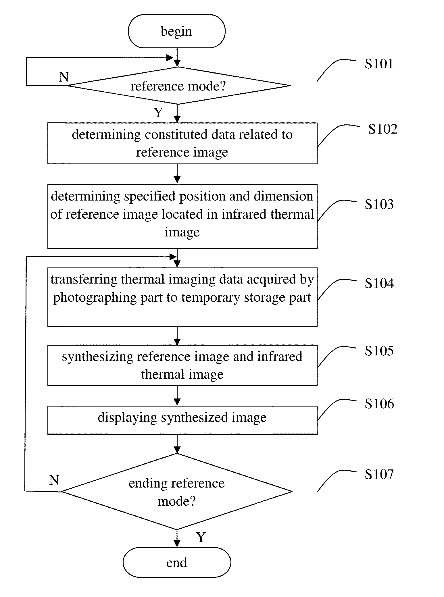
[0142]In step S304, the morphological constituted data acquired by the processing is stored, and the data (the morphological constituted data) acquired by the cutting is stored in the specified area of the temporary storage part 4. In the embodiment, the morphological constituted data acquired by the processing may also be stored in the storage card 6 or the flash memory 7, or the setting mode in the fourth embodiment may be entered.

[0143]In step S305, the morphological constituted data acquired by the processing is determined as the constituted data related to the reference image.

[0144]The control part 10 as the reference image determining part determines the morphological constituted data acquired by the processing and stored in the storage part (such as the temporary storage part 4) as the constituted data related to the reference image.

[0145]In step S306, the specified position and the specified dimension of the reference image located in the infrared thermal image are determine...


PUM


Abstract

This invention provides a thermal imaging device and a thermal image photographing method. In the prior art, when the thermal imaging device is used, a photographing part, photographing angle, and photographing distance of a photographed object are selected according to subjective experience of users, thus lowering photographing speeds and having omissions, and a position, dimension, and angle of thermal images of similar photographed objects in infrared thermal images photographed each time are different, causing subsequent analysis trouble. In this invention, via a reference image with a specified position and specified dimension presented in the infrared thermal image and reflecting specified morphological characters of the photographed object, a visual reference of predetermined thermal image quality and photographing requirements of the photographing object is provided, assisting the users to correctly grasp imaging states and photographing distances of the thermal image, thereby acquiring uniform normative thermal image of the photographed object.

Description

BACKGROUND OF THE INVENTION[0001]1. Field of the Invention[0002]This invention relates to a thermal imaging device, a thermal image processing device, and an infrared detection field and, more particularly, to a thermal imaging device and a thermal image photographing method.[0003]2. Description of the Related Art[0004]As prior art, a thermal imaging device is used for imaging by receiving infrared radiation energy of a photographed object, and a user determines a temperature state of the photographed object according to a displayed infrared thermal image. Each photographed object has specific requirements of a photographing part, a photographing angle, and a photographing distance, and a thermal image of the photographed object conforming to the requirements presents a specific imaging shape.[0005]Since thermal imaging detection technology is applied, users are always confused of recognition of the imaging shape of the photographed object and control of the photographing distance a...

Claims


Application Information

Patent Timeline
IPC IPC(8): H04N5/33H04N5/262H04N5/232H04N5/265H04N9/64
CPCH04N5/33H04N5/265H04N5/2621H04N5/23232H04N9/646G01J2005/0077H04N23/635H04N23/951
Inventor WANG, HAO
Owner MISSION INFRARED ELECTRO OPTICS TECH
Why Eureka
Try Eureka