
Method for controlling emmission in an x-ray imaging device

a technology of x-ray imaging and x-ray, which is applied in the field of controlling the x-ray emission of an x-ray imaging device, can solve the problems of inflexibility, inability to adapt, and inability to precisely solve the problem, and achieve the effect of reducing the x-ray dos

Inactive Publication Date: 2015-02-05
GENERAL ELECTRIC CO
View PDF5 Cites 2 Cited by
  • Summary
  • Abstract
  • Description
  • Claims
  • Application Information

AI Technical Summary

Benefits of technology

This solution enables automatic and systematic control of X-ray emission parameters, achieving high image quality with minimized X-ray dose exposure to the patient, particularly during specific phases of a procedure, by optimizing emission parameters based on real-time data from the imaging process.

Problems solved by technology

Health regulations require the bunting of unnecessary exposure of patients to X-rays which, at high dose, are harmful for the body.
However, this solution is scarcely precise, not flexible and cannot be adapted to every type of procedures being performed in the patient.
However, this solution offers little advantage since it requires manual selection by the practitioner.
Thus, the selection of a single protocol does not allow optimized control to be obtained over the emission parameters for each phase of the procedure.
Manual selection for each phase would also be difficult to implement for the practitioner.

Method used


Image

  • Method for controlling emmission in an x-ray imaging device
  • Method for controlling emmission in an x-ray imaging device
  • Method for controlling emmission in an x-ray imaging device

Examples


Embodiment Construction

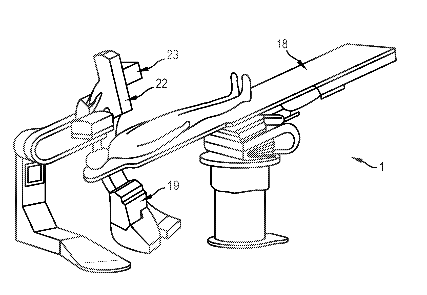
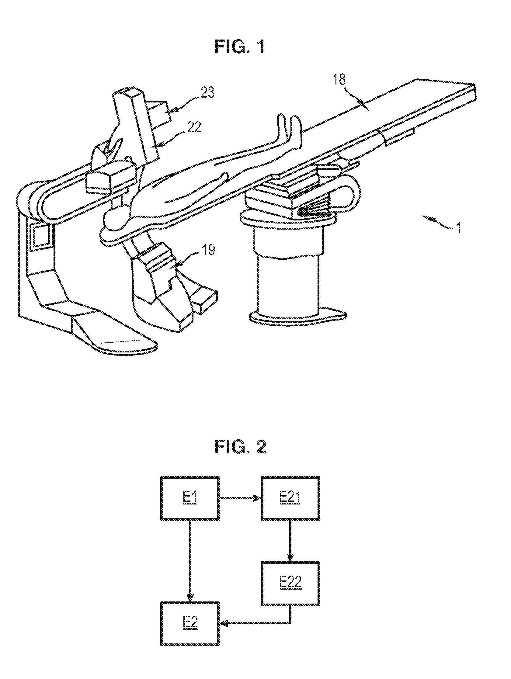
[0021]FIG. 1 illustrates an X-ray imaging device 1 according to an embodiment of the present invention. The device is adapted to take images of a patient's body. As is conventional in the art, the device 1 comprises a table 18 on which a patient is positioned. Generally, the patient lies down on the table 18 when images are taken by the device 1.

[0022]The device 1 comprises an X-ray emitter 19 capable of emitting X-rays towards the patient's body. In general, the emitter 19 comprises a vacuum tube comprising an anode and a cathode, in which a filament, typically a coiled tungsten wire, is heated to high temperature by means of an electric current. The beam of electrons generated by the cathode is accelerated towards the anode. The interaction between the incident beam of electrons and the material of the anode allows the generation of X-rays.

[0023]The X-rays pass through the patient's body and are collected by a detector 22 allowing an image of the patient's body to be obtained.

[002...


PUM


Abstract

A method for controlling the emission of an X-ray imaging device configured to take images of a patient's body, into which a medical instrument has been inserted, is provided. The method comprises: processing at least one image of the patient's body taken by the X-ray imaging device to extract information representing the instrument, wherein the at least one image comprises the instrument; and adapting X-ray emission parameters of the X-ray imaging device, depending on the information extracted from the at least one image, to minimize the X-ray dose emitted towards the patient's body.

Description

CROSS-REFERENCE TO RELATED APPLICATIONS[0001]This application is a continuation of U.S. patent application Ser. No. 13 / 351,823, filed Jan. 17, 2012, which claims foreign priority benefits to French Application No. 1150345 filed Jan. 17, 2011, now French Patent No. 1150345B1, all of which are incorporated by reference herein in their entireties.BACKGROUND OF THE INVENTION[0002]1. Field of the Invention[0003]Embodiments of the present invention relate to a method for controlling the X-ray emission of an X-ray imaging device, and an X-ray imaging device capable of implementing the method.[0004]2. Description of the Prior Art[0005]X-ray imaging devices are used in numerous medical applications. More particularly, these devices are used in interventional radiography, which allows a practitioner to monitor the conducting of a procedure being performed on a patient. Interventional radiology is notably used in vascular surgery in neurology and cancerology.[0006]In these devices, an emitter ...

Claims


Application Information

Patent Timeline
Patent Type & Authority Applications(United States)
IPC IPC(8): A61B6/00A61B6/04A61B6/12
CPCA61B6/544A61B6/12A61B6/5217A61B6/547A61B6/481A61B6/5294A61B6/0407A61B6/5282
Inventor GORGES, SEBASTIENDESPONDS, LIONELBISMUTH, VICENT
Owner GENERAL ELECTRIC CO
Learn More