Linear actuator and vacuum control device

a technology of vacuum control valve and actuator, which is applied in the direction of spindle sealing, mechanical equipment, valve operation means/release devices, etc., can solve the problems of failure to cope with a low flow rate, difficulty in using the poppet-type vacuum control valve in the vacuum chamber, etc., to improve the rigidity of the cover, improve the electrical insulation properties of the sintered body, and the plasma resistance is high

Active Publication Date: 2015-02-05
CKD
View PDF2 Cites 12 Cited by
  • Summary
  • Abstract
  • Description
  • Claims
  • Application Information

AI Technical Summary

Benefits of technology

[0015]According to the third implementation, since the cover comprises an electrically insulating sintered body formed through firing of an electrically insulating nonmetallic material, the cover can have high plasma resistance by virtue of excellent electrically insulating properties of the sintered body. Also, the employment of the sintered body improves rigidity of the cover to thereby effectively restrain deterioration in a sealing structure, and can contribute to a reduction in the surface area (improvement in density) of the cover. That is, the employment of the sintered body having a smooth surface as the cover can restrain an increase in surface area which could otherwise result from surface roughness.
[0016]Meanwhile, the inventors of the present invention have found the following: even though anode oxidation film is formed on the surface of an aluminum moving member, and pore-filling is performed on the anode oxidation film, the surface of the moving member still has a large number of pits and projections. Thus, through employment of the sintered body whose surface is less roughened as compared with the anode oxidation film, the amount of gas adsorption on the cover can be markedly reduced.

Problems solved by technology

However, since controllability of operation of the pendulum-type valve body is low in a low flow rate region (low conductance region), the pendulum-type vacuum control valve involves a problem of failure to cope with a low flow rate of etching gas.
Since the bellows is made of metal and, thus, does not have plasma resistance, difficulty is encountered in using the poppet-type vacuum control valve in a vacuum chamber which handles plasma.

Method used


Image

  • Linear actuator and vacuum control device
  • Linear actuator and vacuum control device
  • Linear actuator and vacuum control device

Examples


first embodiment

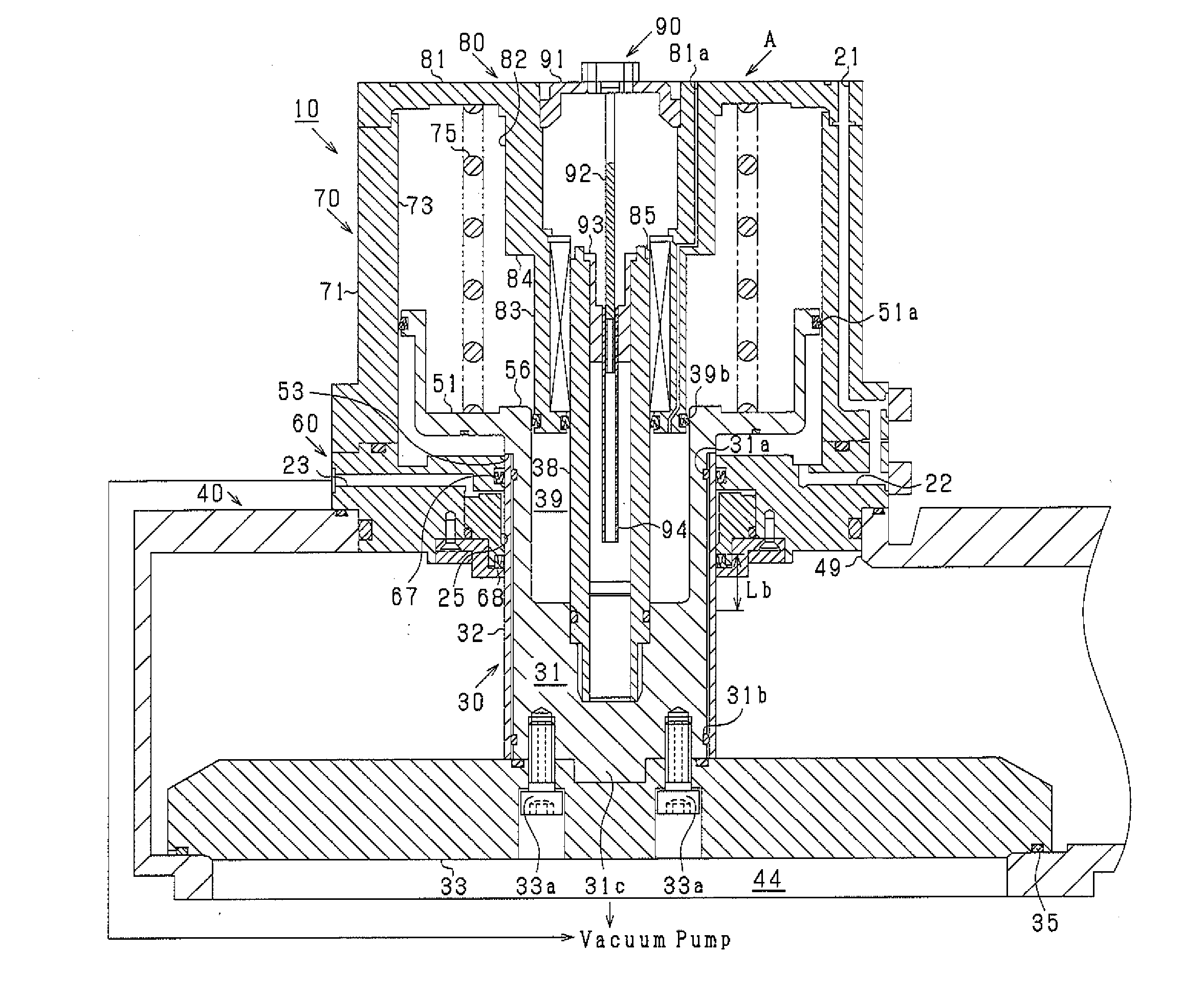
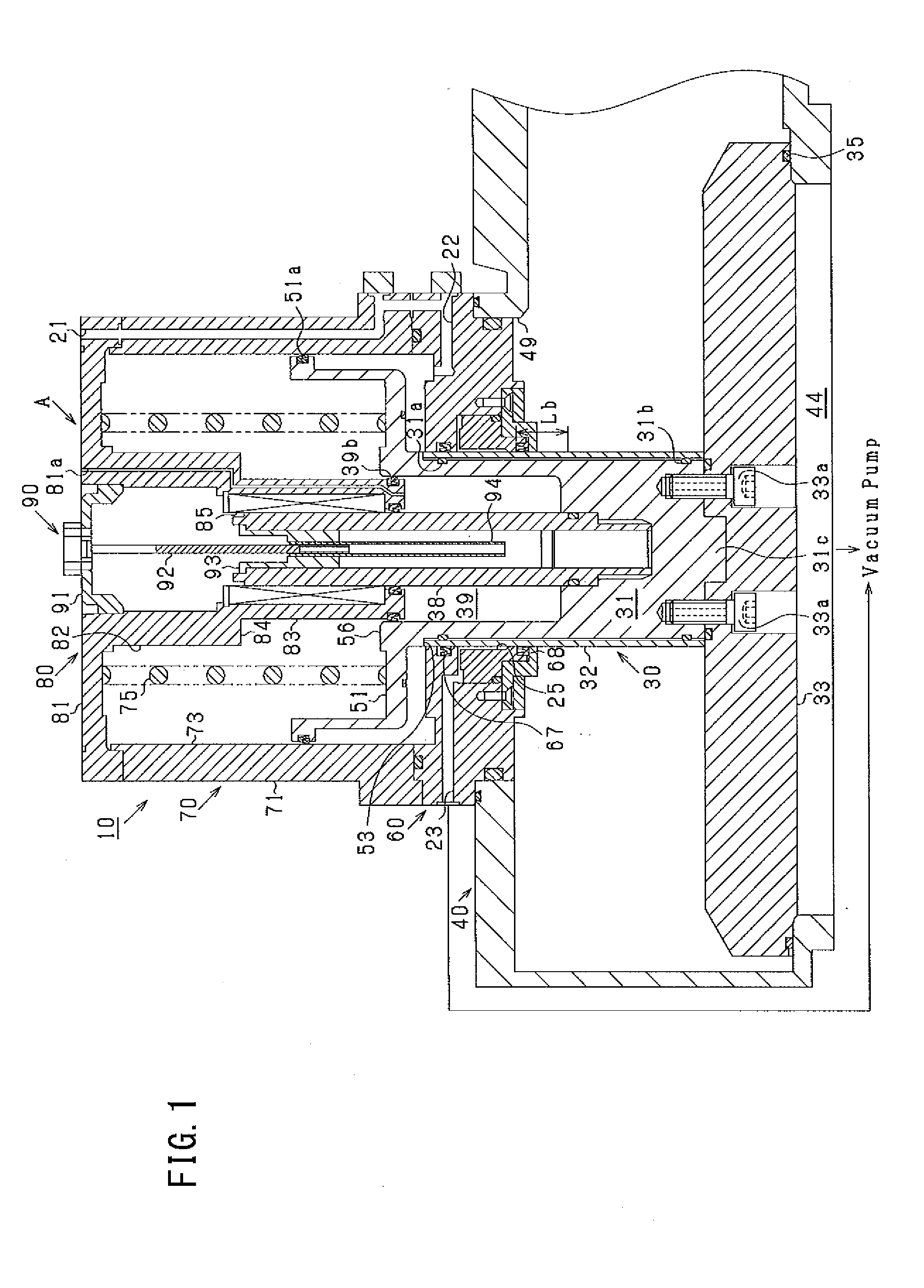
[0064]The piston rod 31 has an attachment section 31c provided at an end portion (lower end portion in FIG. 1) located toward the interior of the vacuum chamber 40. A central portion of the attachment section 31c protrudes in the moving direction of the piston rod 31 (downward in FIG. 1). In the first embodiment, the piston rod 31 and the attachment section 31c are formed integrally from a metal material; specifically, aluminum. The valve body 33 is fixed to the piston rod 31 by use of a plurality of bolts 33a. The attachment section 31c and the piston rod 31 may be separate members.

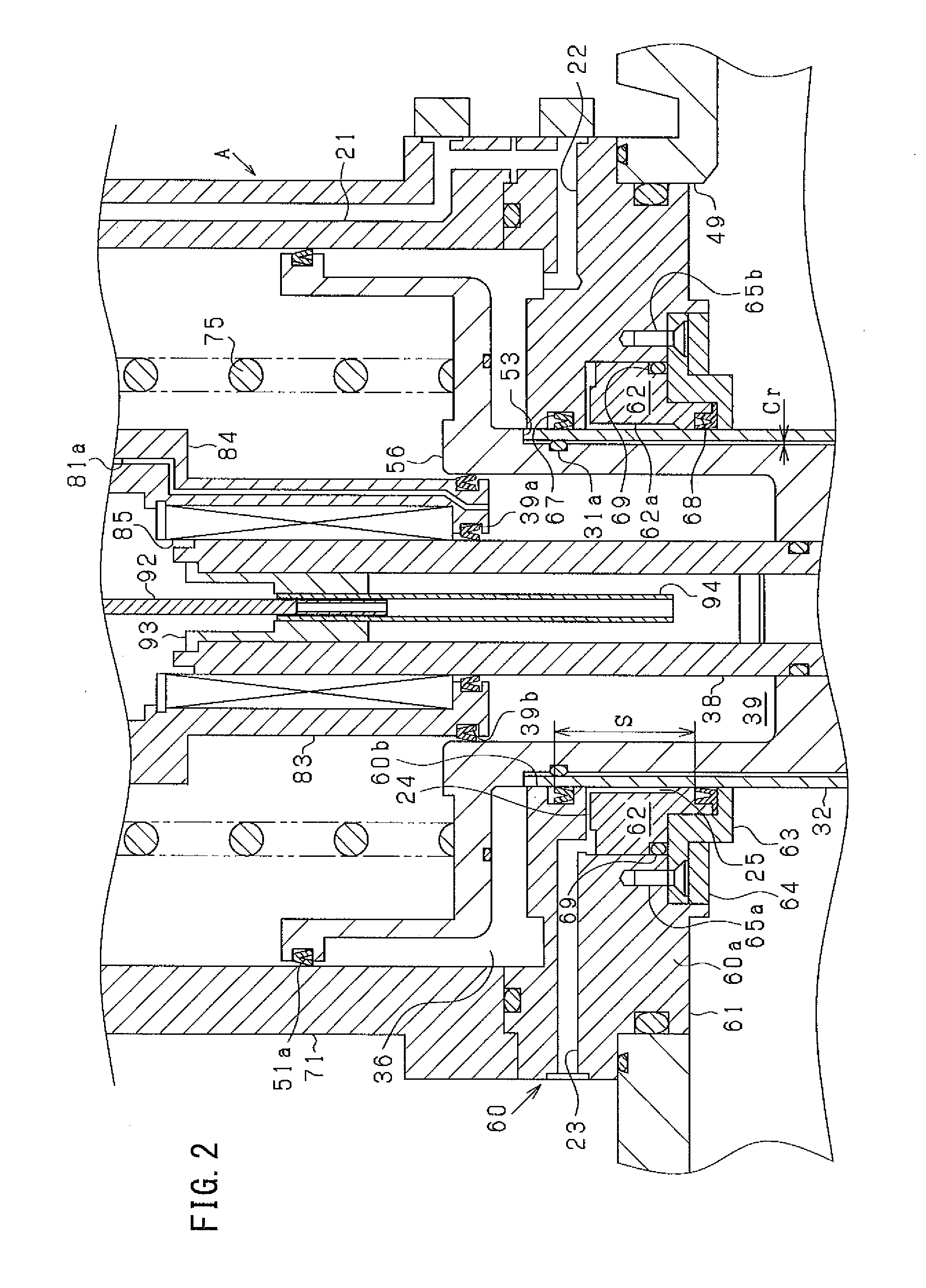
[0065]The piston rod 31 has a cylindrical space formed therein and opening at an end surface located opposite the attachment section 31c. The cylindrical space forms a shutoff load generating chamber 39 for generating force to urge the piston rod 31 and the valve body 33 toward the valve seat 43 (see FIG. 2). The specific constitution of the cylindrically shaped member 32 will be described later.

[0066]Th...

second embodiment

[0116]For example, as shown in FIG. 8, according to the present invention, a linear actuator B rectilinearly (vertically in FIG. 8) moves an arm (operation member) 80 which can work within the vacuum chamber 40. As shown in FIG. 9, the arm 80 handles workpieces (not shown), such as substrates, to be etched within the vacuum chamber 40. The arm 80 is composed of an arm body 80a and a pair of arm pieces 80b attached pivotably (in an opening adjustable manner) to the arm body 80a and handles a workpiece by use of the two arm pieces 80b.

[0117]The linear actuator B according to the second embodiment has an insertion passage 95 which extends through the guide rod 38, the piston rod 31 and the attachment section 31c in the moving direction of the piston rod 31. The probe attachment section 91 provided in the first embodiment is not attached to the head cover 81. One end of the insertion passage 95 opens to the atmosphere in the exterior of the vacuum chamber 40 (the exterior of the cylind...


PUM


Abstract

A linear actuator is used with a vacuum chamber in which plasma is generated. The linear actuator comprises a moving member extending between the exterior and the interior of the vacuum chamber through an opening provided in the vacuum chamber so as to be rectilinearly reciprocated, a drive section configured to reciprocate the moving member, a cover that covers the moving member, and a slide seal section that provides a seal between the interior and the exterior of the vacuum chamber while allowing the cover to slide thereon. The cover covers a range of the moving member which is moved into both of the interior and the exterior of the vacuum chamber while the moving member is reciprocated by the drive section, and an outer surface of the cover is smaller in the amount of gas adsorption per unit area than an outer surface of the moving member.

Description

CLAIM OF PRIORITY[0001]This application is a Continuation of International Patent Application No. PCT / JP2013 / 055545, filed on Feb. 28, 2013, which claims priority to Japanese Patent Application No. 2012-097700, filed on Apr. 23, 2012, each of which is hereby incorporated by reference.BACKGROUND OF THE INVENTION[0002]1. Field of the Invention[0003]The present invention relates to a linear actuator and a vacuum control device for use with a vacuum chamber in which plasma is generated.[0004]2. Description of the Related Art[0005]Manufacturing semiconductor devices involves a process which uses plasma; for example, plasma etching. In the plasma etching process, for example, a vacuum control valve controls a vacuum pressure in a vacuum chamber while allowing etching gas to flow. A vacuum is controlled through adjustment of conductance of the vacuum control valve. In the case of a pendulum-type vacuum control valve used widely in plasma etching, valve opening is adjusted through operation...

Claims


Application Information

Patent Timeline
Patent Type & Authority Applications(United States)
IPC IPC(8): F16J1/01F15B15/14F16J13/18F16K31/122F16K51/02H05H1/46
CPCF16J1/01F15B15/1461F16K31/1221F16K41/04F16K51/02
Inventor KOUKETSU, MASAYUKIITAFUJI, HIROSHI
Owner CKD
Why Eureka
Try Eureka