
Communication draw-in system, communication draw-in method, and communication draw-in program

Active Publication Date: 2015-01-29
NEC CORP
View PDF7 Cites 26 Cited by
  • Summary
  • Abstract
  • Description
  • Claims
  • Application Information

AI Technical Summary

Benefits of technology

The patent aims to make it easy for robots and humans to communicate with each other. The technical effect of this invention is to promote smooth communication between robotic and human platforms.

Problems solved by technology

The use of a mobile robot that approaches a human to communicate with him or her has a safety problem, as there is a possibility that the robot collides with an obstacle.

Method used


Image

  • Communication draw-in system, communication draw-in method, and communication draw-in program
  • Communication draw-in system, communication draw-in method, and communication draw-in program
  • Communication draw-in system, communication draw-in method, and communication draw-in program

Examples


exemplary embodiment 1

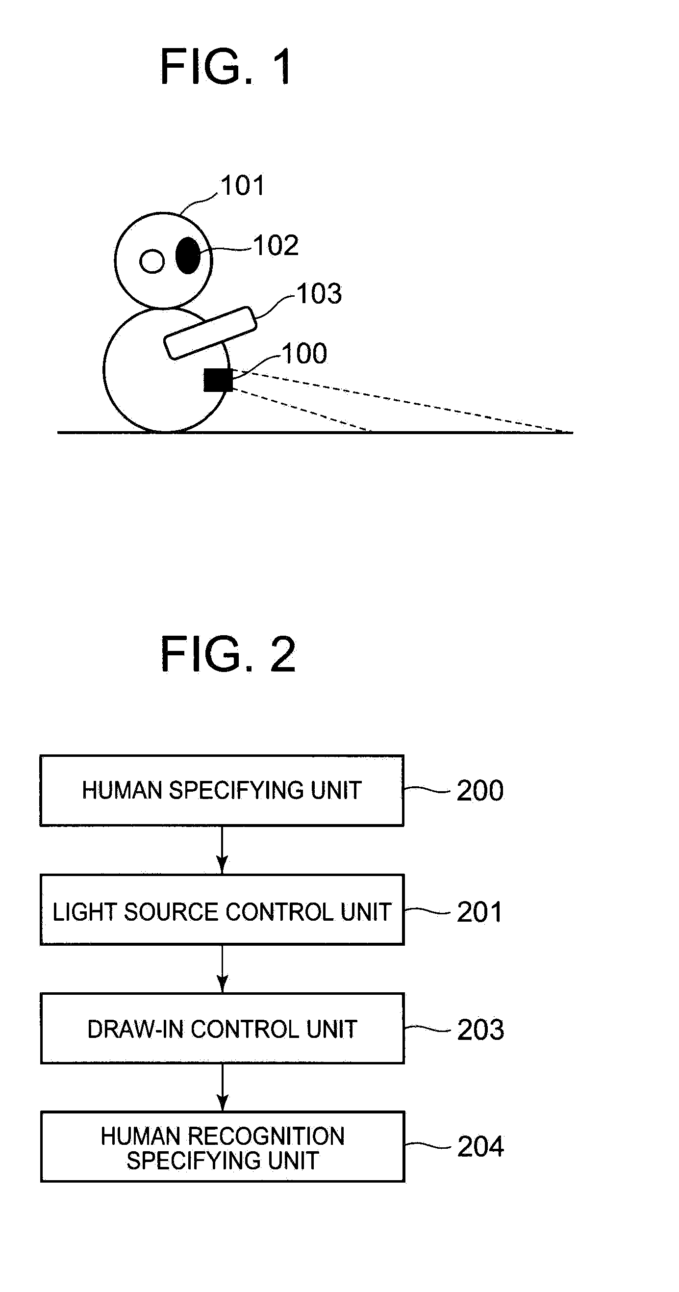
[0019]FIG. 1 is a schematic diagram depicting the appearance of a robot using Exemplary Embodiment 1 (first exemplary embodiment) of a communication draw-in system according to the present invention. The robot depicted in FIG. 1 has an appearance from which one expects the robot to perform communication, and includes a projection module 100, a head 101, a sensing module 102, and an arm 103.

[0020]The projection module 100 includes a light source, and can apply light or project an image onto a floor, a wall, or the like. The projection module 100 has a projection angle adjustable by machine control, and is capable of projection to a specific location.

[0021]The sensing module 102 specifies the locations of the light source and a target human (hereafter also referred to as “human”) to be communicated with, and determines whether or not the target human is aware of light emitted from the light source. For example, the sensing module 102 can be realized by a camera, an infrared sensor, or...

exemplary embodiment 2

[0049]The following describes an example of using remote communication by an operator, as another exemplary embodiment of the communication draw-in system according to the present invention. In the following, the description of the same structures and operations as those in Exemplary Embodiment 1 is omitted. FIG. 6 is a schematic diagram depicting the appearance of a robot using Exemplary Embodiment 2 (second exemplary embodiment) of the communication draw-in system according to the present invention. The robot depicted in FIG. 6 includes a communication module 105 in addition to the structure of the robot depicted in FIG. 1, and is connected to a personal computer (PC) 106 via a network 107.

[0050]The communication module 105 is a communication interface capable of network connection. The network 107 is a wireless LAN as an example. The PC 106 is not a limitation of the type of device, and any device connectable to the network may be used. Examples of such a device include a mobile ...


PUM


Abstract

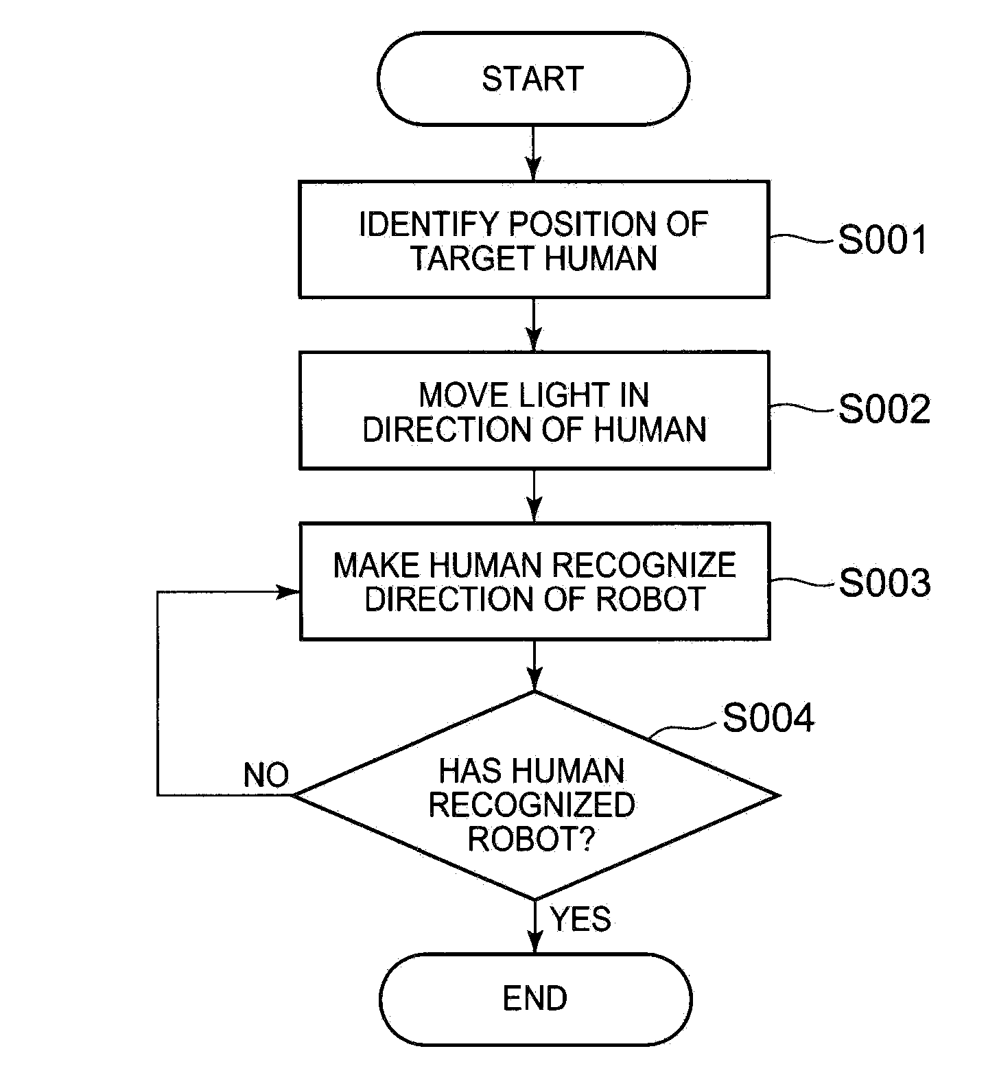
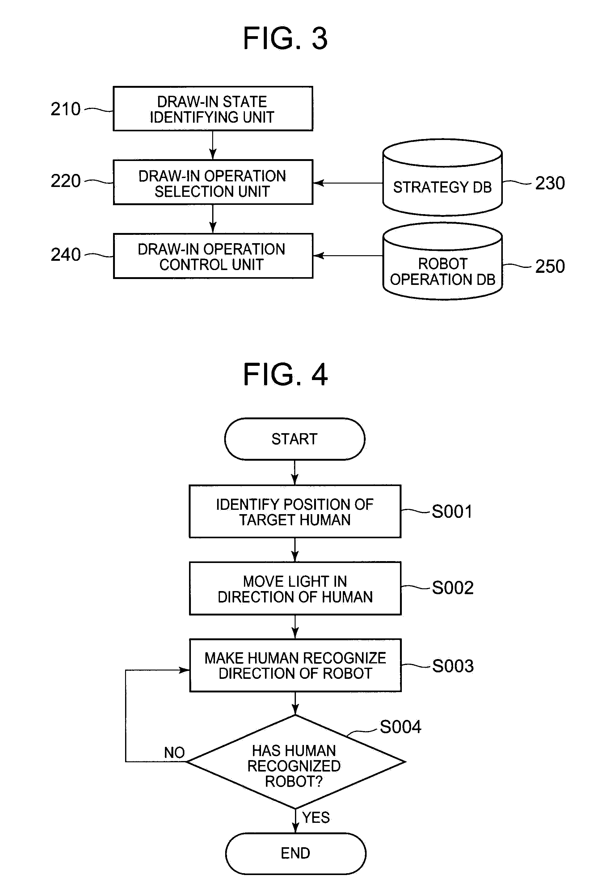
A communication draw-in system that enables robot-human communication to start smoothly is provided. The communication draw-in system is a communication draw-in system provided in a robot that communicates with a target human, and includes: a human specifying unit 200 for specifying a position of the target human; a light source control unit 201 for moving light toward the specified position of the target human; a draw-in control unit 203 for instructing the robot to perform a draw-in operation for making the target human recognize a direction of the robot; and a human recognition specifying unit 204 for determining whether or not the target human has recognized the robot, wherein the robot is instructed to start communicating with the target human, in the case where the target human is determined to have recognized the robot.

Description

TECHNICAL FIELD[0001]The present invention relates to a communication draw-in system used for a robot that communicates with humans.BACKGROUND ART[0002]Social needs for robots have been increasing, and robots that communicate with humans have been developed. To start communication such as interaction, a robot needs to have mutual understanding for starting the communication with a target human who the robot is to communicate with.[0003]Robots capable of locomotion (hereafter referred to as “mobile robots”), such as a humanoid robot with two legs and a wheeled robot, have also been developed. The use of a mobile robot that approaches a human to communicate with him or her has a safety problem, as there is a possibility that the robot collides with an obstacle. To solve the safety problem, Patent Literature (PTL) 1 discloses a technique for improving safety by allowing a human to visually recognize a dangerous range that varies as the operation of a mobile robot changes.[0004]For stat...

Claims


Application Information

Patent Timeline
IPC IPC(8): B25J9/16
CPCB25J9/1602Y10S901/47Y10S901/01B25J11/0005B25J13/08
Inventor ISHIGURO, SHIN
Owner NEC CORP
Learn More