
Electronic brake system and control method thereof

a technology of electronic brakes and control methods, applied in the direction of brake action initiation, brake systems, transportation and packaging, etc., can solve the problems of physical shock being transferred to the brake pedal connected to the input rod, kickback phenomenon, irregular internal pressure of the master cylinder, etc., to improve ride comfort and driving stability.

Active Publication Date: 2015-01-29
HL MANDO CORP
View PDF7 Cites 18 Cited by
  • Summary
  • Abstract
  • Description
  • Claims
  • Application Information

AI Technical Summary

Benefits of technology

The present invention provides an electronic brake system and control method that can prevent a pulsation in the brake pedal caused by a kick-back phenomenon in the ABS mode. This is achieved by stopping the backward-movement of the ball screw to prevent the output rod from colliding with the input rod. This invention improves ride comfort and driving stability and prevents the risk of brake pedal pulsation.

Problems solved by technology

However, in an ABS mode, the brake oil in the master cylinder may fluctuate and thus internal pressure of the master cylinder may become irregular because of the brake oil returned from the wheel cylinder to the master cylinder.
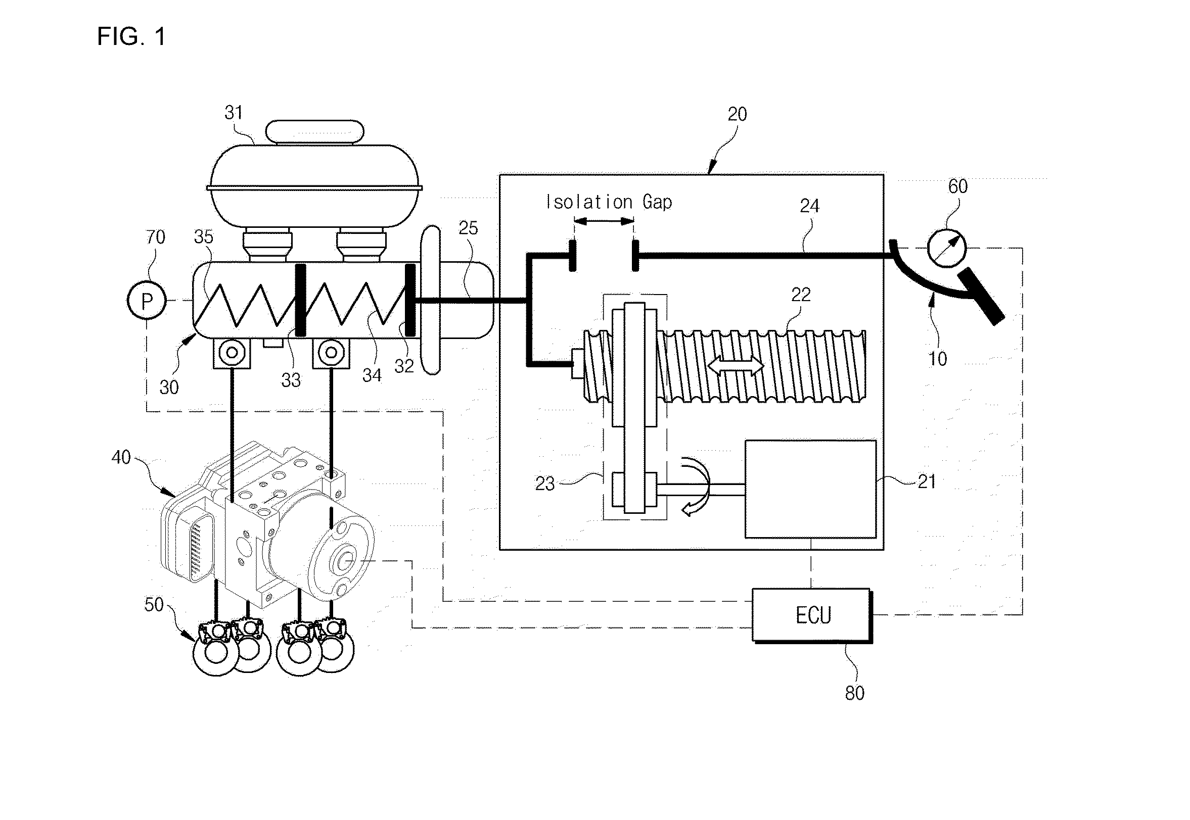
At this time, because the driver keeps pressing on the brake pedal and thus the input rod connected to the brake pedal is in a forward-shifted position, the output rod may move a distance beyond the isolation gap and may collide with the input rod, which results in a kick-back phenomenon such that a physical shock is transferred to the brake pedal connected to the input rod due to collision with the output rod.
Such a kick-back phenomenon may cause a driver to experience a pulsation in the brake pedal, thereby giving the driver an unpleasant feeling.

Method used


Image

  • Electronic brake system and control method thereof
  • Electronic brake system and control method thereof
  • Electronic brake system and control method thereof

Examples


Embodiment Construction

[0033]Reference will now be made in detail to the preferred embodiments of the present invention, examples of which are illustrated in the accompanying drawings. The preferred embodiments described in the specification and shown in the drawings are illustrative only and are not intended to represent all aspects of the invention, such that various equivalents and modifications can be made without departing from the spirit of the invention. In the following description of the present invention, a detailed description of known functions and configurations incorporated herein will be omitted when it may make the subject matter of the present invention rather unclear. In the drawings, the widths, the lengths, the thicknesses, etc. of elements may be exaggerated for convenience of description. Further, in the drawings, the same or similar elements are denoted by the same reference numerals even though they are depicted in different drawings.

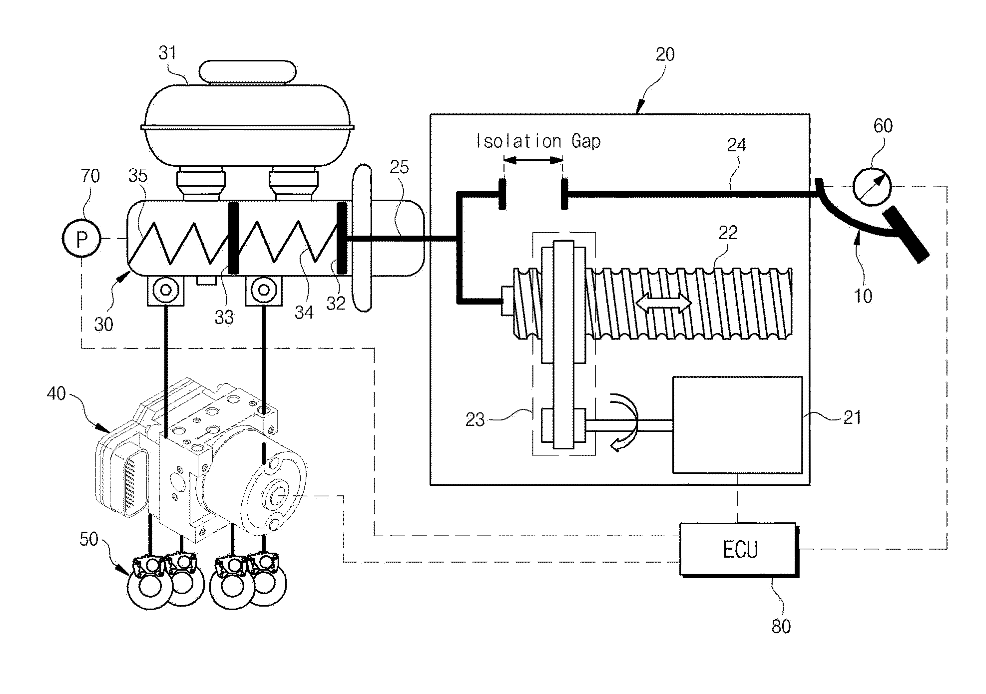
[0034]FIG. 1 is a conceptual view to explain con...


PUM


Abstract

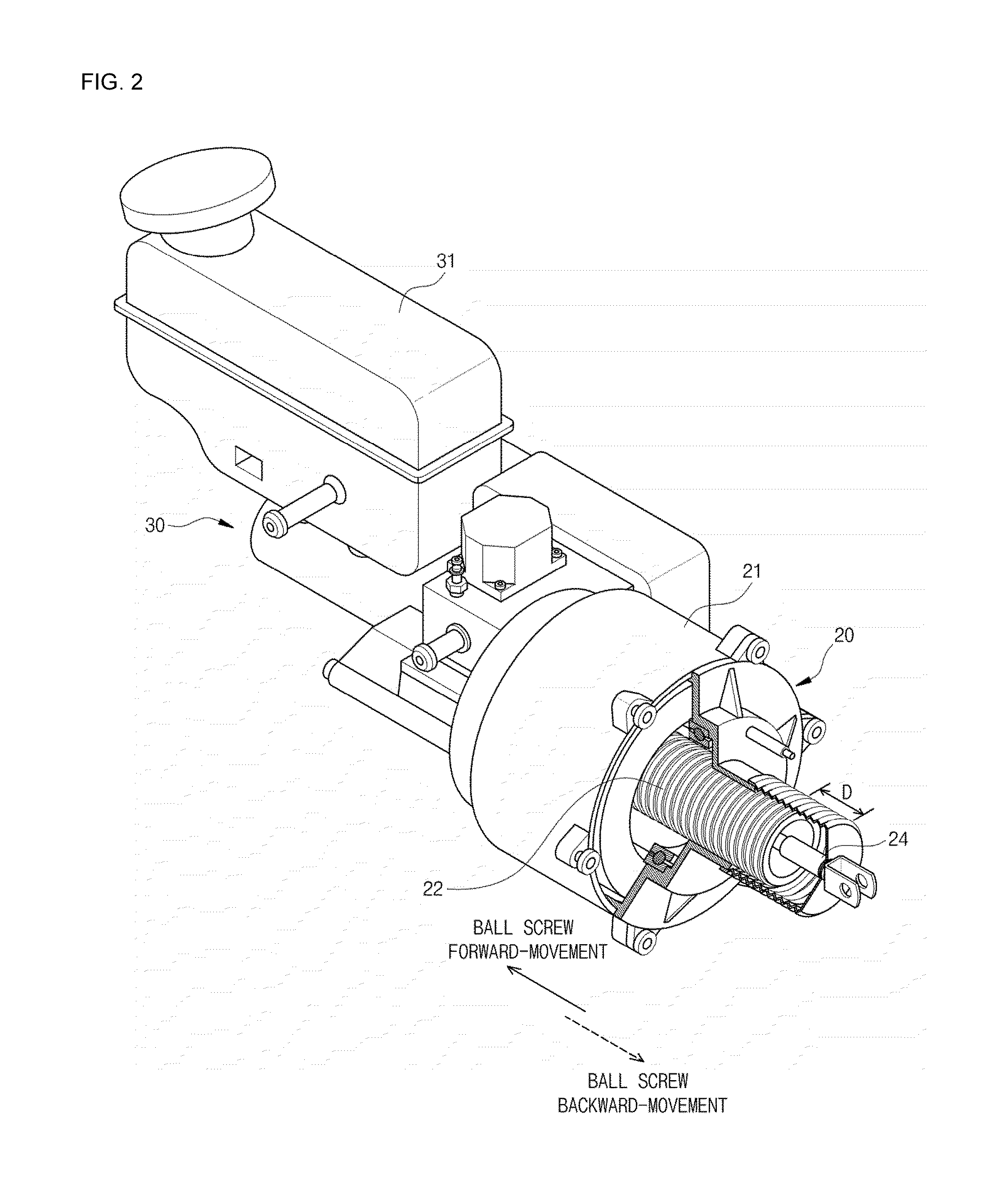
Disclosed are an electronic brake system and a control method thereof. The electronic brake system includes a master cylinder including a piston, an output rod contacting the piston, an input rod configured to be moved forward by a driver's manipulation of a brake pedal and arranged coaxially to the master cylinder and spaced a predetermined isolation gap apart from the output rod, an electrically-driven booster including a motor, a ball screw to move the output rod, and a motion converting unit to move the ball screw forward and backward by converting rotational movement of the motor into linear movement, and an electronic control unit (ECU) to control operation of the motor based on the size of the isolation gap. When the ball screw is moved backward in an ABS mode, the ECU stops backward-movement of the ball screw before the output rod collides with the input rod.

Description

CROSS-REFERENCE TO RELATED APPLICATION[0001]This application claims the benefit of Korean Patent Application No. 2013-0087719, filed on Jul. 25, 2013 in the Korean Intellectual Property Office, the disclosure of which is incorporated herein by reference.BACKGROUND[0002]1. Field[0003]Embodiments of the present invention relate to an electronic brake system and a control method thereof, and more particularly to, an electronic brake system and a control method thereof capable of adjusting pressure of a master cylinder using an electrically-driven booster.[0004]2. Description of the Related Art[0005]Typically, in an electronic brake system including an electrically-driven booster, when a driver presses on a brake pedal, a pedal force sensor detects pedal force of the driver and an electronic control unit (ECU) drives a motor of the electrically-driven booster based on the detection result of the pedal force sensor to deliver multiplied force to a master cylinder. The master cylinder tra...

Claims


Application Information

Patent Timeline
IPC IPC(8): B60T13/74B60T7/04
CPCB60T7/042B60T13/745B60T8/4077B60T11/16B60T13/74
Inventor CHOI, KYU-WOONG
Owner HL MANDO CORP
Learn More