Subframe structure and vibration damper for the same

Inactive Publication Date: 2006-03-09
SUMITOMO RUBBER IND LTD +1
View PDF9 Cites 30 Cited by
  • Summary
  • Abstract
  • Description
  • Claims
  • Application Information

AI Technical Summary

Benefits of technology

[0015] It is therefore an object of the present invention to provide a subframe structure of novel construction, which is capable of simply providing a mechanism that can detect, more accurately and more rapidly, external forces acting on automobile wheels. It is also another object of the invention to provide a rubber mount that can be used in this subframe structure.
[0016] More specifically, the object of the present invention is to provide a subframe structure that is suitable for use as structural element in a vehicle control system, as a structure that detects signals for control in a vehicle control system, such as for controlling traction or controlling vehicle stability, and in antilock braking systems sued in order to improve the stability of travel of vehicles, and to provide a rubber mount that can be used in this subframe structure.

Problems solved by technology

However, in a structure that is provided with embedded deformation gauges, equipped in holes in the axles, as described in the aforementioned JP-B-2628444, such structure are difficult to commercialize when one considers the strength and structure of the axles and when one considers manufacturability.
In practice, since it is necessary to provide a plurality of holes in the axles in order to detect forces in a plurality of directions, there is a problem in that commercialization is all the more difficult.
Moreover, in a structure that is arranged for sensing deformation, rotation, etc., of the tire from the outside through the provision of detector targets on the tire, such as described in the aforementioned JP-A-2001-191767, there are problems in that there is the risk that the performance of the tire will be compromised by the installation of the detection targets added to the tire.
In addition to the problem of the likelihood of damage to the detection targets from flying gravel, mud, etc., from the surface of the road, and while the speed of rotation of the wheel can be detected easily, there is a problem in that it is extremely difficult to calculated, from the detected values, the external forces acting on the wheels.
Furthermore, in a structure that is arranged so as to detect, using position sensors, or the like, this location of the disk of the rim wheels through elastic linkage of a rim wheel to a disk part, as described in the aforementioned JP-A-2002-316502, the rigidity of the wheel itself is reduced by the necessity of the elastic linkage of the rim wheel to the disk part, which may have a negative impact on the stability of travel.
Furthermore, since the sensor is located in a position that is extremely near to the tire, there is a problem in the ease with which the sensor may be damaged by gravel, mud, etc., thrown up from the road surface.
This requires a large number of detector positions, which is not only disadvantageous in terms of cost, but also problematic in terms of the difficulty of calculation.
Moreover, not only is the behavior of the tire complex, but the suspension parts undergo relatively large dislocations depending on the behavior of the tire to dislocate in the direction of the load that is applied to the suspension bushing.
In some cases there are load inputs not only in the axial direction of the bushing and in a direction that is perpendicular to the axial direction of the bushing, but also input loads in a flexing direction and in the twisting direction, thus leading to the possibility of the occurrence of relatively large errors even in the calculation results that estimate the external forces that act on the wheels.
Therefore, when there are disruptions to the alignment of the suspension parts, due to impact loads on the wheels, there will also be deviations in the load detection of the suspension bushings, which can cause errors in the estimates of the external forces that act on the wheels.

Method used


Image

  • Subframe structure and vibration damper for the same
  • Subframe structure and vibration damper for the same
  • Subframe structure and vibration damper for the same

Examples


Embodiment Construction

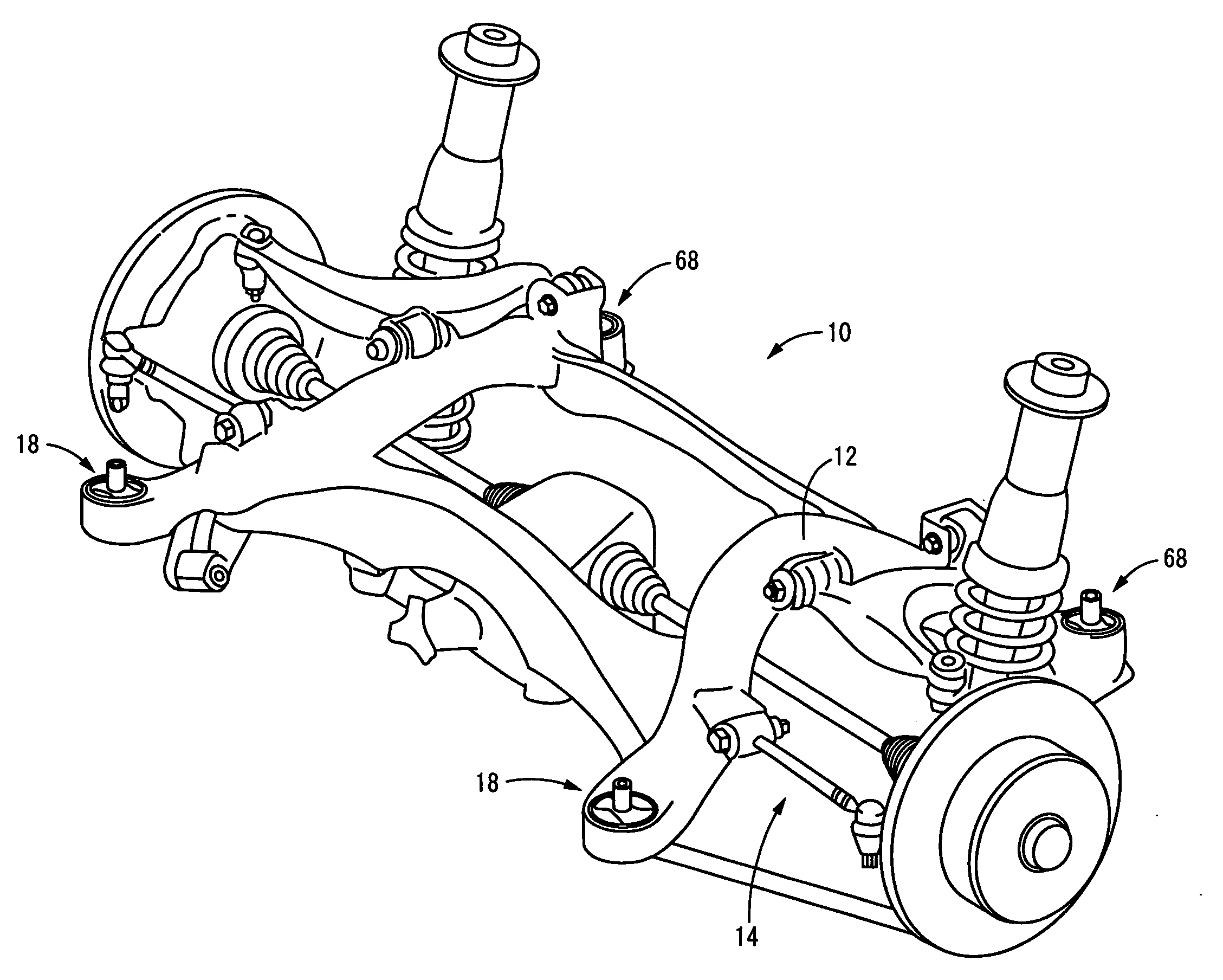
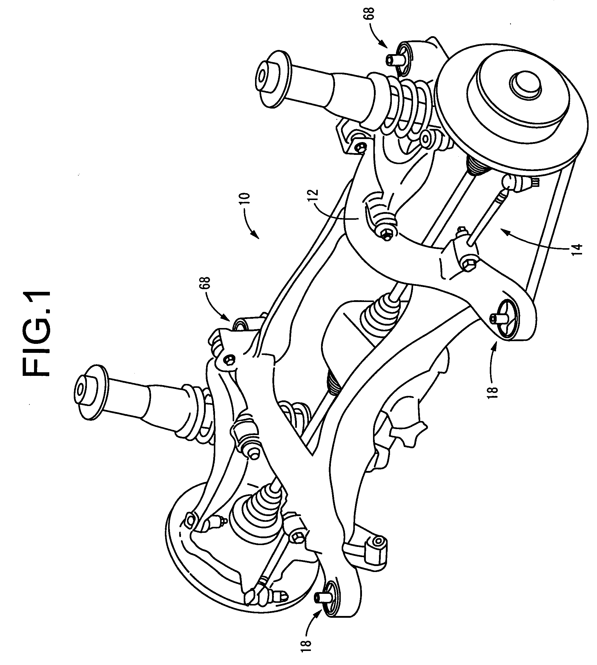
[0041]FIG. 1 illustrates a subframe structure 10 of construction according to a first embodiment of the present invention. The subframe structure 10 comprises a subframe 12, through which a rod, a ring, an arm, and other suspension components 14 are held connected to a vehicle body of an automotive vehicle.

[0042] The subframe 12 is formed of a steel member having a high stiffness, and is a member that has, overall, an essentially rectangular frame member shape. The suspension components 14, which support each of the wheels 16, are attached to this subframe 12. The subframe 12 is also attached to the vehicle body through a plurality of rubber mounts, e.g., four subframe mounts 18, 18, 68, and 68 in the present form of embodiment.

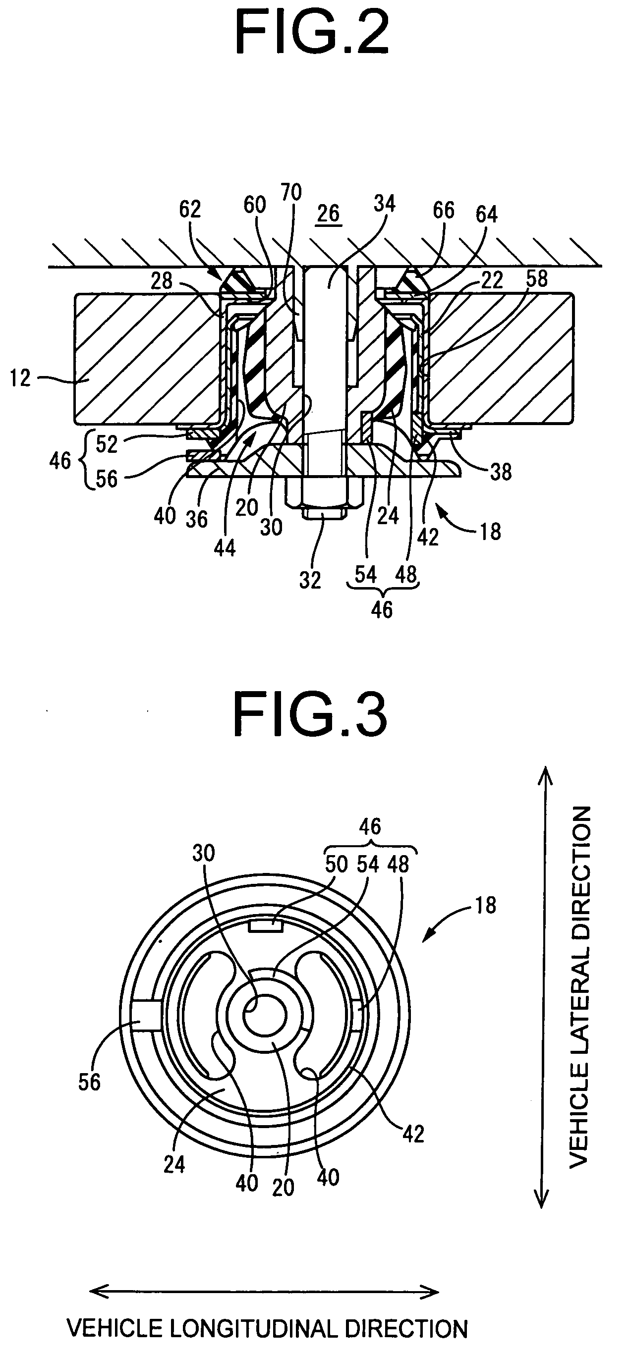
[0043] As shown in FIGS. 2 and 3, this subframe mount 18 has a structure wherein a metallic inner sleeve 20 functioning as an inner rod member, and a metallic outer sleeve 22 functioning as an outer cylinder member, are connected elastically by a rubber ela...


PUM


Abstract

A subframe structure for an automotive vehicle wherein a subframe is attached through a rubber mount to a vehicle body, suspension components are assembled onto the subframe so that the suspension components are held connected to the vehicle body through the subframe, and a detecting assembly capable of providing an output signal according to a load that acts between a subframe and a vehicle body is provided. A rubber mount for use in this subframe structure is also disclosed.

Description

INCORPORATED BY REFERENCE [0001] The disclosure of Japanese Patent Application No. 2004-262429 filed on Sep. 9, 2004 including the specification, drawings and abstract is incorporated herein by reference in its entirety. BACKGROUND OF THE INVENTION [0002] 1. Field of the Invention [0003] The present invention relates to a vibration damper structure for subframes installed in automobiles, and to a subframe structure using the same. More particularly, the invention is concerned with a subframe structure equipped with detecting assembly for providing a signal for use as a detection signal for control in systems for controlling the state of travel of automobiles, and to rubber mounts for use in the subframe structure. [0004] 2. Description of the Related Art [0005] There has long been research into suppressing unstable vehicle body behavior, such as slipping, through providing mechanical supplementation to the steering by the driver in order to improve the stability of motion of automob...

Claims


Application Information

Patent Timeline
IPC IPC(8): B62D21/11B60G7/00B60G17/00B60G17/019B60T8/171B62D21/00F16F15/08G01L5/00G01L5/16
CPCB60G7/02B60G2200/1322B60G2200/144B60G2200/445B62D21/11B60G2204/4104B60G2206/0114B60G2206/602B60G2206/604B60G2204/15
Inventor KATAGIRI, AKIRAYAMADA, TAKEHIROMIYOSHI, AKIHIROTSURITA, TAMIOSUZUKI, MOTOSHI
Owner SUMITOMO RUBBER IND LTD
Why Eureka
Try Eureka