Illuminated intra-oral delivery device

a delivery device and intra-oral light technology, applied in the field of automatic lighting system, can solve the problems of difficult alignment of external light sources to the injection site, failure to provide a practical means for illuminating, and difficulty in seeing an injection site inside the mouth

Inactive Publication Date: 2015-01-22
SABOURIN CHRISTOPHER R
View PDF8 Cites 22 Cited by
  • Summary
  • Abstract
  • Description
  • Claims
  • Application Information

AI Technical Summary

Benefits of technology

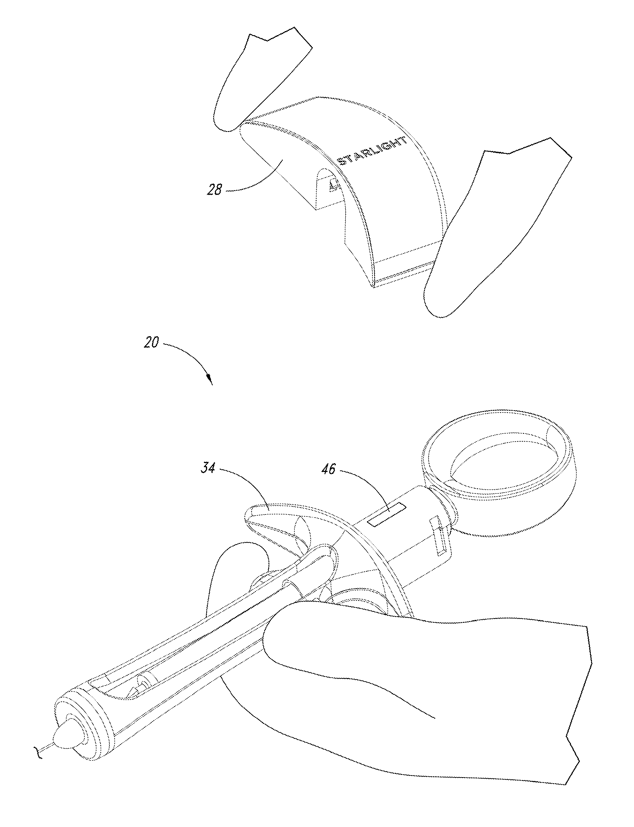
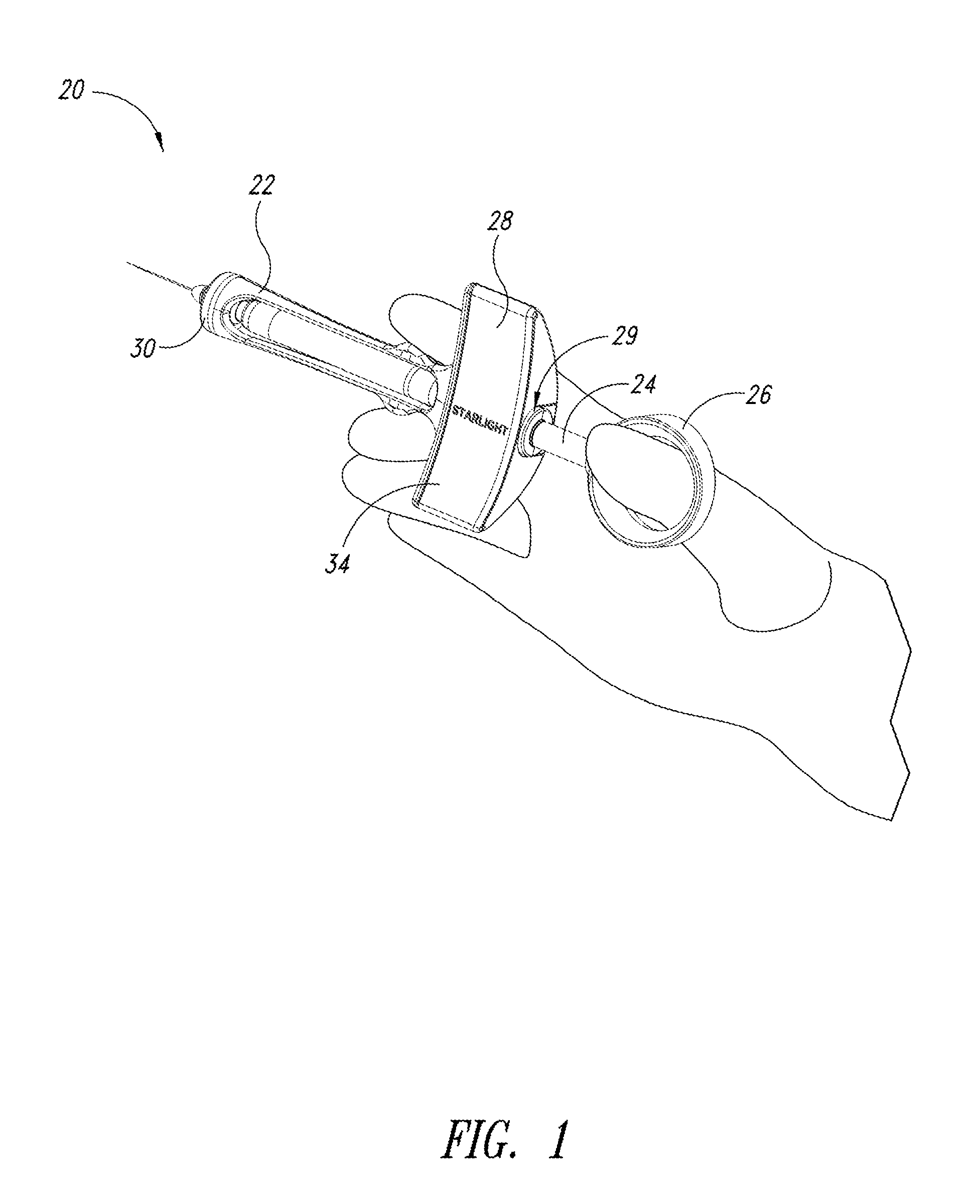
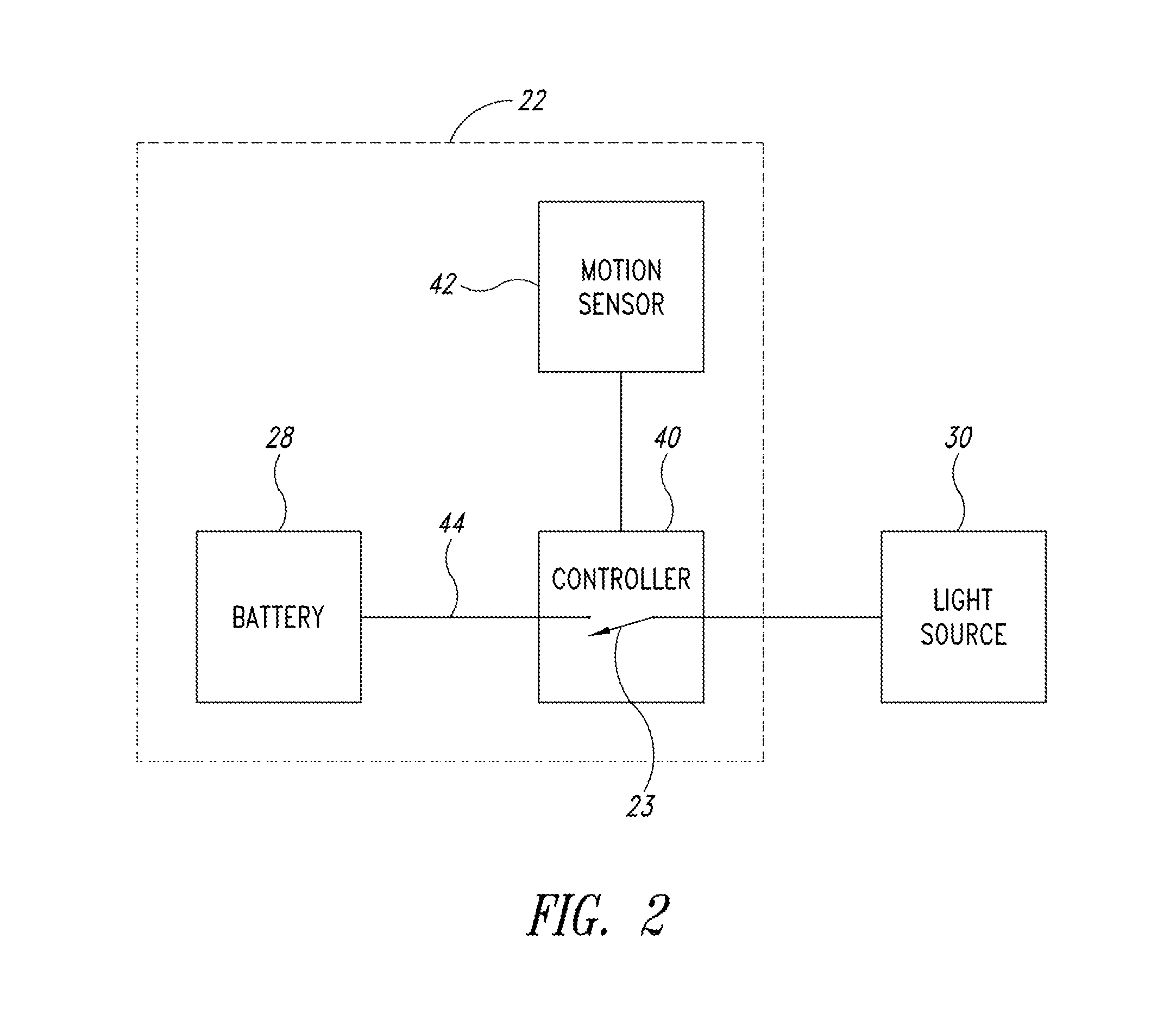
The present patent discloses an illuminated syringe for use in medical and dental fields. The syringe includes a light source that is powered by a battery and controlled by a control circuit that detects motion. The light source can be activated when the syringe is picked up and can blink when the battery reaches the level of discharge. The syringe has a battery pack that can be easily mounted on it and decoupled from the light source when the syringe is no longer moving. The technical effects of this invention include improved visibility during medical and dental procedures and improved maneuverability of the syringe in low-light settings.

Problems solved by technology

Because of the small opening of the mouth, it can be difficult to see an injection site inside the mouth.
The space constraints of a patient's mouth also make it difficult to align an external light source to the injection site.
However, these syringes fail to provide a medical practitioner with a practical means for illuminating an injection site.
In addition, a practitioner may have several tasks to carry out in order to properly perform the injection, and these tasks may prevent them from operating or focusing on additional devices.
A practitioner therefore may not have the ability or time to control electronics or other additional devices while using the syringe.
In addition, most of these prior designs cannot be sterilized without requiring disassembly and then reassembly prior to the next use.
Moreover, portable sources of power, such as batteries, require partial disassembly to replace the batteries.

Method used


Image

  • Illuminated intra-oral delivery device
  • Illuminated intra-oral delivery device
  • Illuminated intra-oral delivery device

Examples


Embodiment Construction

[0030]In the following description, certain specific details are set forth in order to provide a thorough understanding of various disclosed embodiments. However, one skilled in the relevant art will recognize that embodiments may be practiced without one or more of these specific details, or with other methods, components, materials, etc. In other instances, well-known structures or components or both associated with syringes, including but not limited to plungers, needles, and carpules and the like have not been shown or described in order to avoid unnecessarily obscuring descriptions of the embodiments.

[0031]Unless the context requires otherwise, throughout the specification and claims that follow, the word “comprise” and variations thereof, such as “comprises” and “comprising” are to be construed in an open inclusive sense, that is, as “including, but not limited to.” The foregoing applies equally to the words “including” and “having.”

[0032]Reference throughout this description ...


PUM


Abstract

A medical syringe with a light source mounted on a distal end of the syringe to provide illumination of an injection site, a battery pack receiver configured to receive a battery pack with magnetic attraction a proximal end of the syringe, and a control circuit that is configured to illuminate the light source when the control circuit detects movement of the syringe and disconnects the battery from the light source either after a fixed period of time or after motion of the syringe ceases. Ideally the light source is a disc-shaped array of LED lights. The syringe is constructed of materials that can be sterilized.

Description

BACKGROUND[0001]1. Technical Field[0002]The present disclosure is directed to the provision of light at an oral injection site and, more particularly, to an automated lighting system adapted for use with syringes.[0003]2. Description of the Related Art[0004]In some health care fields, it is sometimes necessary to perform fluid injections, irrigations, and withdrawals in locations that are dimly lit. In particular, dentists frequently perform anesthetic injections near the back of a patient's mouth. Because of the small opening of the mouth, it can be difficult to see an injection site inside the mouth. The space constraints of a patient's mouth also make it difficult to align an external light source to the injection site.[0005]One proposed solution has been to create a syringe that utilizes a light source at the needle end of the syringe in order to allow for better illumination of an injection site. Some of these syringe designs include light sources that are located remotely from...

Claims


Application Information

Patent Timeline
IPC IPC(8): A61C19/08
CPCA61C19/08A61C1/088A61C1/0015A61C17/0202A61M5/24A61M5/3129A61M5/315A61M2205/80A61M2205/8206
Inventor SABOURIN, CHRISTOPHER, R.
Owner SABOURIN CHRISTOPHER R
Why Eureka
Try Eureka