
Hybrid-scavenger, separator system and method

a technology of separator system and hybrid scavenger, which is applied in the field of hybrid scavenger, separator system and method, can solve the problems of increasing fluid dynamic drag, reducing below one percent or into parts per million of oil in water or water in oil is unheard, and reducing the fraction of oil in water. , the effect of maximizing the amount of disposal

Inactive Publication Date: 2015-01-22
THOUGHT PRESERVE LLC
View PDF6 Cites 1 Cited by
  • Summary
  • Abstract
  • Description
  • Claims
  • Application Information

AI Technical Summary

Benefits of technology

The invention is a method and apparatus for separating oil from water and oil from gas using a conventional separator, such as a gunbarrel separator. The invention includes a scavenger system that optimizes the efficiency of the system by supporting overdriving, de-rating, or both of the separator. The scavenger system includes hybrid scavengers that require less throughput than the entire system but still support a high level of separation. The scavengers are designed to remove contaminants from the oil and water, improving the quality of the oil and water for disposal. The invention also includes optimizing the use of the disposal permit by overdriving the separator beyond its design capacity and using back-washable oil filters to remove traces of the lighter species. The scavengers are designed to remove contaminants from the oil and water, improving the performance and longevity of the injection well. The invention is suitable for optimizing the overall system by supporting the separation process and improving the quality of the oil and water for disposal.

Problems solved by technology

Removal of solids, petroleum products, and the like assist in resisting fouling of the well, which would increase fluid dynamic drag on the injected flow as well as eventually sealing off the well and rendering it unsuitable for continued injection.
Reducing below one percent or into parts per million of oil in water or water in oil is unheard of in the industry.
Economics of equipment and throughputs would make such a concept irrational.
Less water content in oil improves the quality thereof, and therefore the price.
Since injection wells have an allowed capacity, literally permitted by governmental permit, fouling a well destroys valuable capacity permitted for disposal in that well.

Method used


Image

  • Hybrid-scavenger, separator system and method
  • Hybrid-scavenger, separator system and method
  • Hybrid-scavenger, separator system and method

Examples


Embodiment Construction

[0033]It will be readily understood that the components of the present invention, as generally described and illustrated in the drawings herein, could be arranged and designed in a wide variety of different configurations. Thus, the following more detailed description of the embodiments of the system and method of the present invention, as represented in the drawings, is not intended to limit the scope of the invention, as claimed, but is merely representative of various embodiments of the invention. The illustrated embodiments of the invention will be best understood by reference to the drawings, wherein like parts are designated by like numerals throughout.

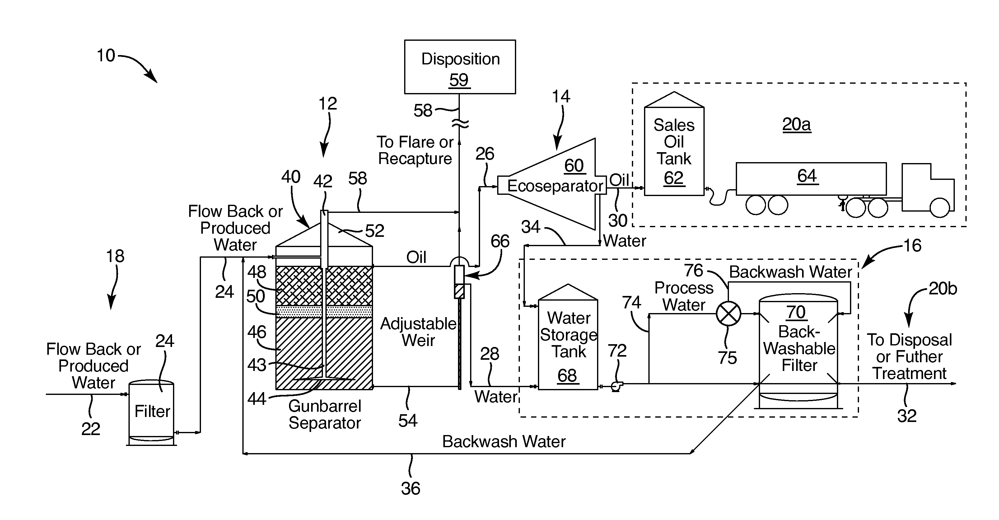
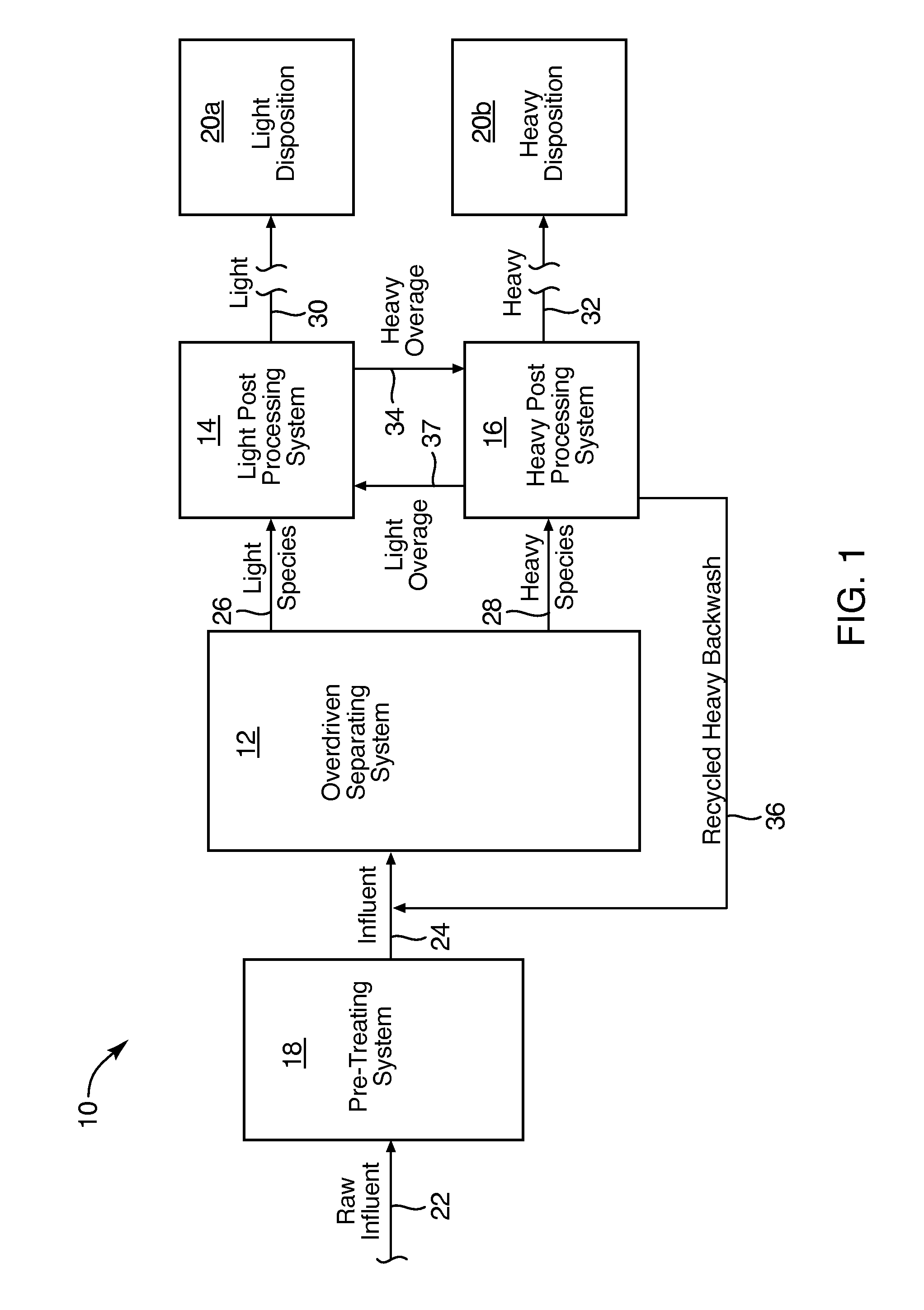
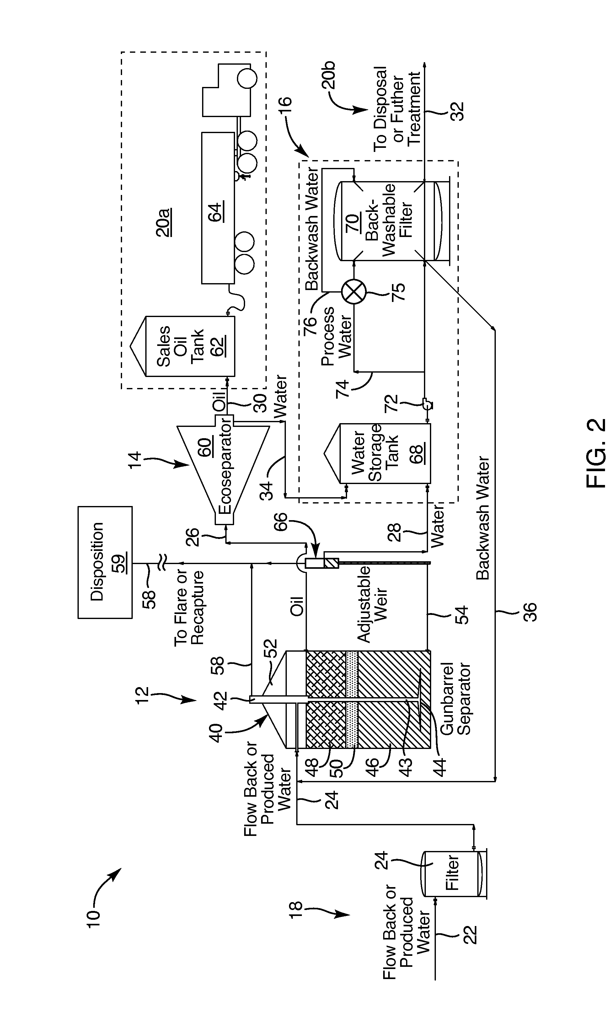
[0034]Referring to FIG. 1, a system 10 in accordance with the invention may have as a central element thereof a separator 12. Separators 12 come in large variety. Cylindrical drum separators are available, settling tanks in a wide variety of configurations exist, and so forth. One suitable separator 12 is called a gunbarrel sepa...


PUM

PropertyMeasurementUnit
contrastaaaaaaaaaa
contrastaaaaaaaaaa
PRESSUREaaaaaaaaaa

Abstract

A hybrid scavenger operates downstream of a separator such as a gunbarrel separator for petroleum production. The separator may be overdriven to maximize use of a permitted reinjection rate. The hybrid scavenger then extracts water from the oil and oil from the water without having to treat the entire stream of incoming production fluids.

Description

RELATED APPLICATIONS[0001]This application: is a divisional application (continuation) of co-pending U.S. patent application Ser. No. 14 / 336,220, filed Jul. 21, 2014, entitled UNVENTED, BACK-PRESSURE-CONTROLLED, LAMINAR-ANNULAR-VELOCITY-DISTRIBUTION, CONTINUOUS CENTRIFUGAL SEPARATOR APPARATUS AND METHOD, which claims the benefit of U.S. Provisional Patent Application Ser. No. 61 / 814,760, filed Apr. 22, 2013, entitled UNVENTED, BACK-PRESSURE-CONTROLLED, LAMINAR-ANNULAR-VELOCITY-DISTRIBUTION, CONTINUOUS CENTRIFUGAL SEPARATOR APPARATUS AND METHOD; is a divisional application (continuation) of co-pending U.S. patent application Ser. No. 14 / 104,970, filed Dec. 12, 2013, entitled DYNAMIC, INFLUENT-CONSTITUENT-BASED, SEPARATOR CONTROL APPARATUS AND METHOD, which claims the benefit of U.S. Provisional Patent Application Ser. No. 61 / 814,760, filed Apr. 22, 2013, entitled UNVENTED, BACK-PRESSURE-CONTROLLED, LAMINAR-ANNULAR-VELOCITY-DISTRIBUTION, CONTINUOUS CENTRIFUGAL SEPARATOR APPARATUS AND ...

Claims


Application Information

Patent Timeline
Patent Type & Authority Applications(United States)
IPC IPC(8): C02F1/20B01D17/02C02F1/38
CPCB01D17/0217B01D17/0214C02F1/38C02F2301/022C02F1/286C02F2101/32C02F2103/10C02F1/20B04B1/04B04B11/02B04B5/0442B04B13/00B01D17/12B04B2013/006B04B1/02C02F1/008C02F1/40C02F2209/03
Inventor MILLER, C. MICHAELBELL, DAVID A.
Owner THOUGHT PRESERVE LLC
Learn More