
Network System, Switch and Method of Network Configuration

Active Publication Date: 2015-01-08
NEC CORP
View PDF6 Cites 42 Cited by
  • Summary
  • Abstract
  • Description
  • Claims
  • Application Information

AI Technical Summary

Benefits of technology

The switch is able to communicate with multiple controllers at the same time, which allows it to switch the network without needing to synchronize with the other controllers. This results in faster and more efficient communication.

Problems solved by technology

Thus, there was a problem in that, when a network size becomes greater, understanding and improving system behavior becomes difficult and designing and reconfiguration are accompanied by an enormous cost.
(1) First subject: in an existing OpenFlow network, a controller (OFC) manages all the switches (OFS); consequently, a load of the controller easily increases and setting flow entry may take time.
In addition, if the controllers are configured in a system with a redundant configuration (such as a fault tolerant system or a cluster system), when the system switches from an active system to a standby system, a status of synchronization between the old active system and the switch (OFS) and a status of synchronization between the new active system and the switch (OFS) has to be made identical, and this process takes time.
However, at present, such technology of making redundant is not established.
However, at present, such technology related to a load balancing is not established.
Therefore, a mechanism of synchronization between controllers (OFC) is necessary and controller (OFC) implementation becomes complicated.

Method used


Image

  • Network System, Switch and Method of Network Configuration
  • Network System, Switch and Method of Network Configuration
  • Network System, Switch and Method of Network Configuration

Examples


Embodiment Construction

[0046]The present invention is targeting a C / U separation type network. Herein, it will be explained about an OpenFlow network which is an example of the C / U separation type network. It should be noted that the present invention is not limited by the OpenFlow network.

Exemplary Embodiment

[0047]Hereinafter, an exemplary embodiment of the present invention will be described by referring to attached drawings.

[0048](System Configuration)

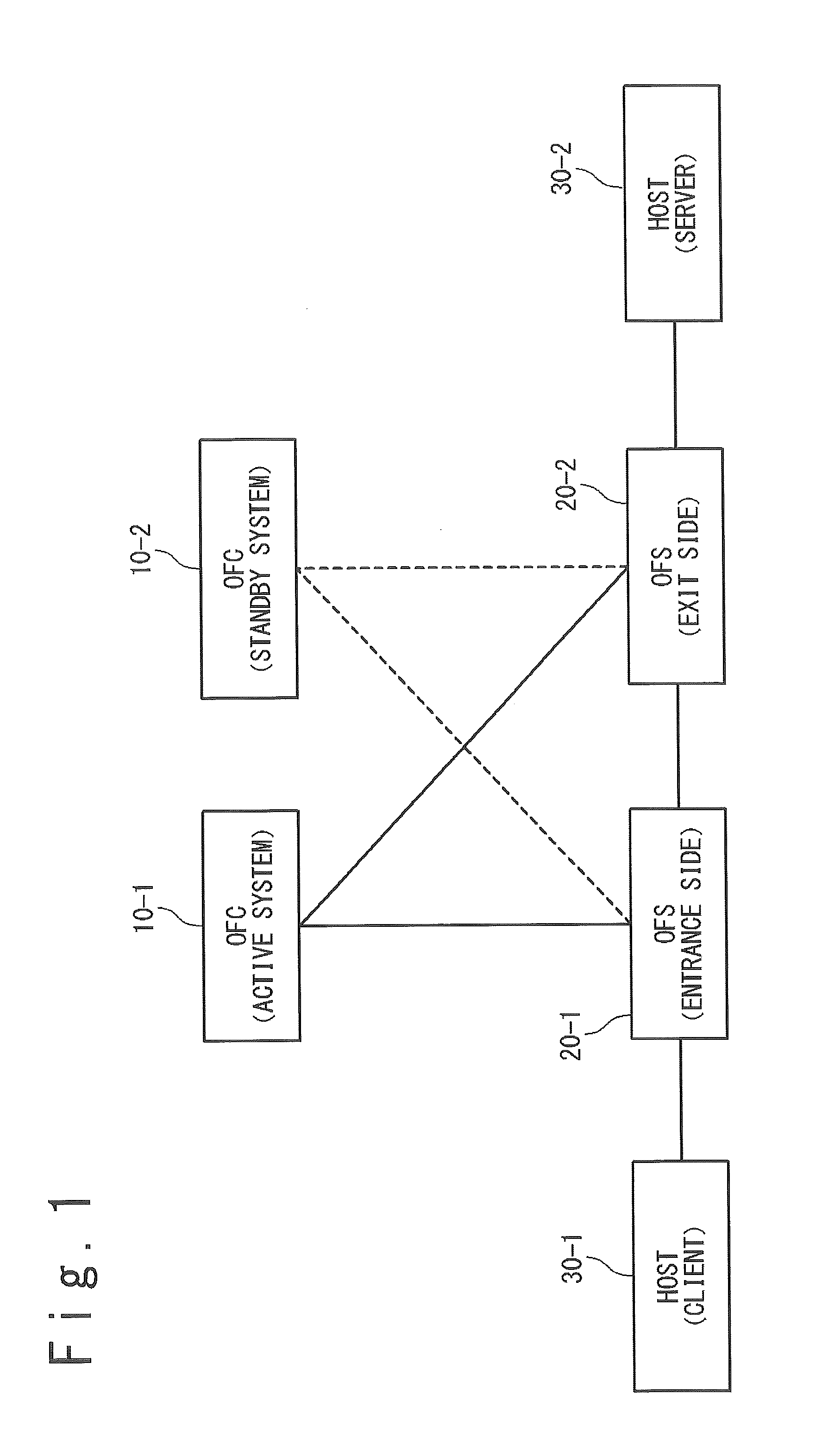
[0049]An example of a configuration of a network system related to the present invention will be described by referring to FIG. 1.

[0050]The network system related to the present invention includes a controller (OFC) 10, a switch (OFS) 20 and a host 30.

[0051]The controller (OFC) 10, the switch (OFS) 20 and the host 30 may be plural. For example, each of a plurality of controllers (OFC) 20 will be denoted switch (OFS) 20-1, switch (OFS) 20-2, . . . , etc. In FIG. 1, a controller (OFC) 10-1, a controller (OFC) 10-2, a switch (OFS) 20-1, a switch (OFS) 20-2, ...


PUM


Abstract

A network system of the present invention includes a switch and controllers. The switch processes on a received packet in accordance with a flow entry in which are defined a rule and an action. The controllers set the flow entry to a flow table of the switch. The switch assigns a flow table to each controller, searches when receiving a packet from outside for a flow table matching with the packet in all flow tables, ignores a flow entry set by a controller of which a status of connection is invalid among flow entries matching with the packet and processes the packet in accordance with an action of a flow entry set by a controller of which a status of connection is valid.

Description

TECHNICAL FIELD[0001]The present invention is related to a network system, especially to a network system in which packet transferring function and path controlling function of network devices are separated.BACKGROUND ART[0002]A conventional network device is a black box and a control rich in flexibility for load balancing or deviation cannot be performed from outside. Thus, there was a problem in that, when a network size becomes greater, understanding and improving system behavior becomes difficult and designing and reconfiguration are accompanied by an enormous cost.[0003]As a technique of resolving such subjects, a method is considered to separate packet transferring function and path controlling function of network devices. For example, by making a network device handle the packet transferring function and making a control apparatus separated outside of the network device handle the controlling function, a control becomes easier and a network rich in flexibility becomes able to...

Claims


Application Information

Patent Timeline
IPC IPC(8): H04L12/851H04L12/935H04L12/813H04L45/42H04L47/20H04L49/111
CPCH04L47/2441H04L49/3009H04L47/20H04L45/64H04L41/042H04L41/0895H04L41/40H04L41/342H04L41/0894H04L41/0893
Inventor MURAKAMI, TAKAHIKO
Owner NEC CORP
Learn More