
Antennas

a technology of antennas and antennas, applied in the field of antennas, can solve the problems of low cost of existing wide-band and wide-area antennas, inability to support both 2.4-2.5 ghz and 4.9-5.9 ghz frequencies, and the inability to provide 180 degree horizontal beamwidth of most commercially available antennas

Inactive Publication Date: 2015-01-08
L COM
View PDF3 Cites 216 Cited by
  • Summary
  • Abstract
  • Description
  • Claims
  • Application Information

AI Technical Summary

Benefits of technology

This patent describes an antenna that includes a dielectric substrate and multiple antenna elements positioned on the surface of the substrate. Each antenna element consists of a sector-shaped sheet of conductive material and a conductive feed line. The antenna elements can be arranged in an arc or at uniform angular intervals along the substrate. A ground layer can be added to the opposite side of the substrate. The antenna can also have a housing. Further, this patent describes a printed-circuit board antenna that includes at least six antenna elements. Overall, this invention provides an improved antenna design that enables efficient communication and signal reception.

Problems solved by technology

Most commercially-available antennas do not provide 180 degree horizontal beamwidth and do not support both 2.4-2.5 GHz and 4.9-5.9 GHz frequencies.
Existing wide-band and wide-area antennas are expensive, which prevents wide adoption.

Method used


Image

  • Antennas
  • Antennas
  • Antennas

Examples


Embodiment Construction

Antennas

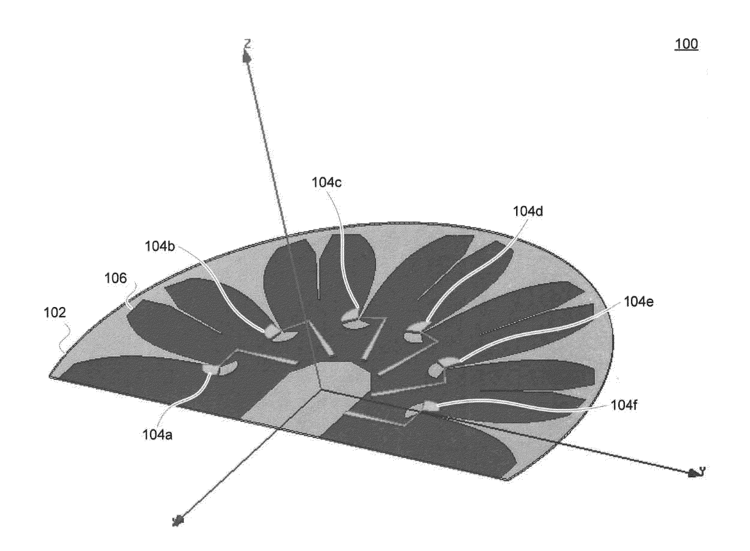
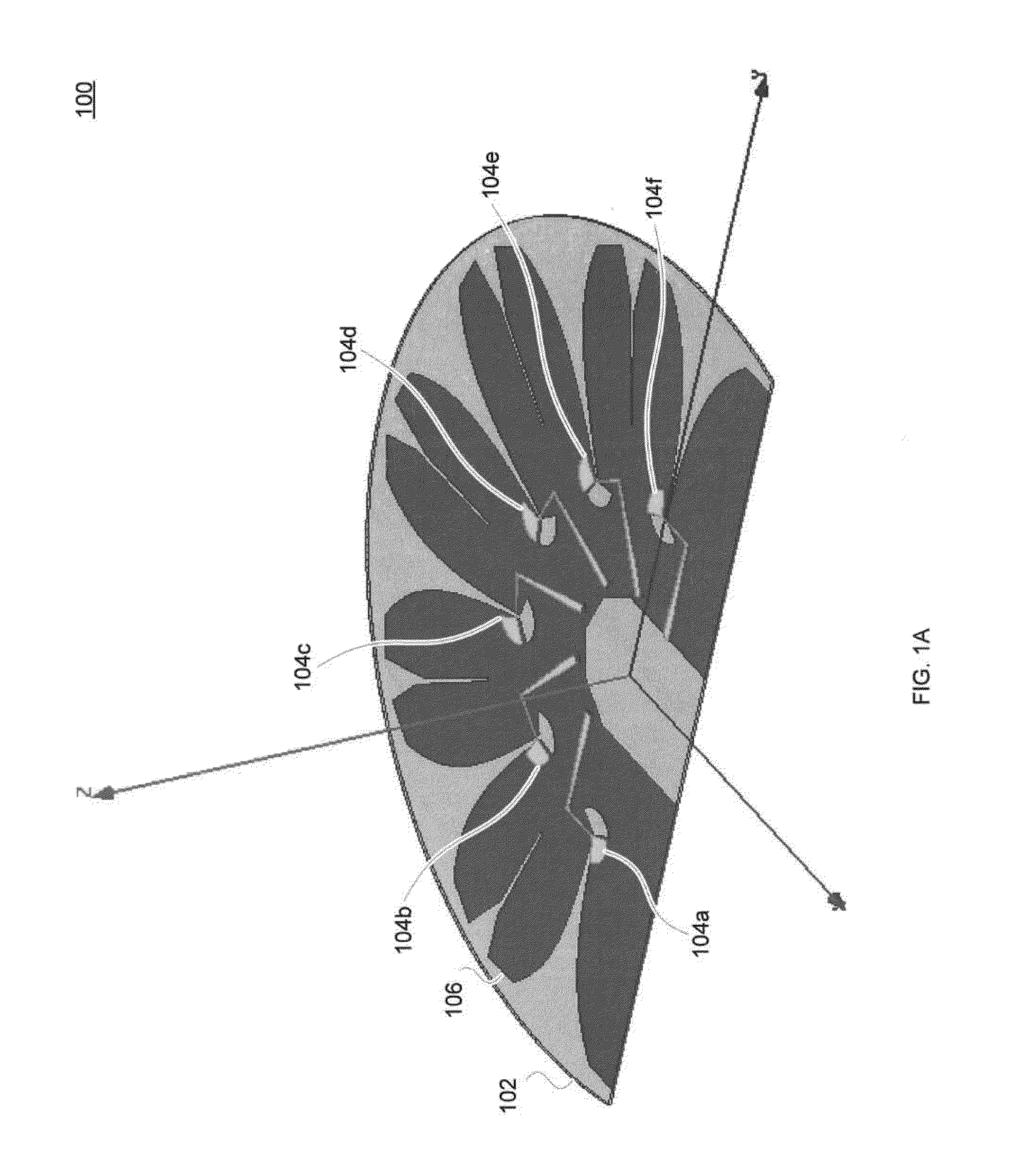
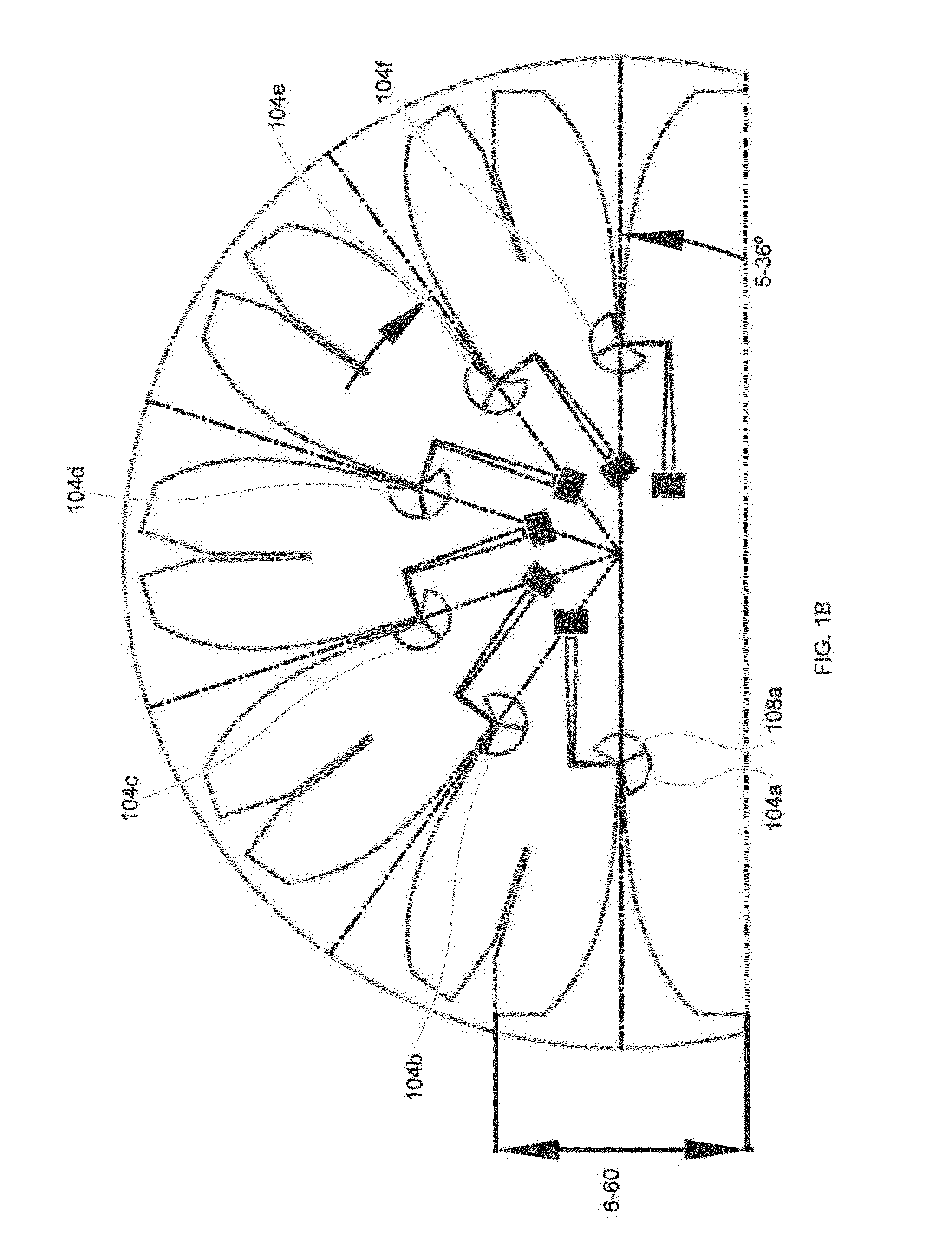
[0044]Referring now to FIGS. 1A-1C, an antenna 100 is provided. Antenna 100 includes a dielectric substrate 102, a plurality of antenna elements 104 (e.g., 2, 3, 4, 5, 6, 7, 8, 9, 10, 11, 12, and the like) positioned on a first surface of the dielectric substrate 102, and a ground layer 106 mounted to an opposite surface of the dielectric substrate 102.

[0045]Dielectric substrate 102 is depicted as substantially transparent in FIGS. 1A and 1B so that the relative positioning of antenna elements 104 with respect to the geometry of ground layer 106 is visible, but can be opaque or translucent as depicted in FIGS. 1B and 1C. Dielectric substrate 102 can be fabricated from a variety of materials used in the manufacturing of electronic devices such as printed circuit boards. For example, dielectric substrate 102 can be fabricated from silicon, silicon dioxide, aluminum oxide, sapphire, germanium, gallium arsenide (GaAs), an alloy of silicon and germanium, indium phosphide (InP), a...


PUM


Abstract

One aspect of the invention provides an antenna including: a dielectric substrate and a plurality of antenna elements positioned on a surface of the dielectric substrate. Each antenna element includes: a sector-shaped sheet of conductive material and a conductive feed line coupled to the sector-shape sheet of conductive material. Another aspect of the invention provides an antenna including: a dielectric substrate, a plurality of antenna elements positioned on a surface of the dielectric substrate at substantially uniform angular intervals along an arc, and a ground layer mounted to an opposite side of the dielectric substrate from the plurality of antenna elements. Each antenna element includes: a sector-shaped sheet of conductive material having a central angle between about 90° and about 180° and a conductive feed line coupled to the sector-shape sheet of conductive material.

Description

CROSS-REFERENCE TO RELATED APPLICATION[0001]This application claims priority to U.S. Provisional Patent Application Ser. No. 61 / 843,653, filed July 8, 2013. The entire content of this application is hereby incorporated by reference herein.BACKGROUND OF THE INVENTION[0002]Along with development of wireless communication, wide-band and wide-area coverage becomes a need of users. Most commercially-available antennas do not provide 180 degree horizontal beamwidth and do not support both 2.4-2.5 GHz and 4.9-5.9 GHz frequencies. Existing wide-band and wide-area antennas are expensive, which prevents wide adoption.SUMMARY OF THE INVENTION[0003]One aspect of the invention provides an antenna including: a dielectric substrate and a plurality of antenna elements positioned on a surface of the dielectric substrate. Each antenna element includes: a sector-shaped sheet of conductive material and a conductive feed line coupled to the sector-shape sheet of conductive material.[0004]This aspect of ...

Claims


Application Information

Patent Timeline
Patent Type & Authority Applications(United States)
IPC IPC(8): H01Q21/00
CPCH01Q21/0075H01Q1/2291H01Q1/42H01Q13/085H01Q21/20
Inventor PESA, PATRICKHONG, TANGZHENLIN, LIAO
Owner L COM
Learn More