
Bonding Apparatus and Method

a technology of mechanical bonding and substrate, which is applied in the direction of bandages, other domestic articles, transportation and packaging, etc., can solve the problems of pattern element chipping, frequent and costly repairs, and high nip pressures that may exceed the compressive yield strength of cold work powder metal tool steels

Active Publication Date: 2014-12-25
THE PROCTER & GAMBLE COMPANY
View PDF1 Cites 107 Cited by
  • Summary
  • Abstract
  • Description
  • Claims
  • Application Information

AI Technical Summary

Benefits of technology

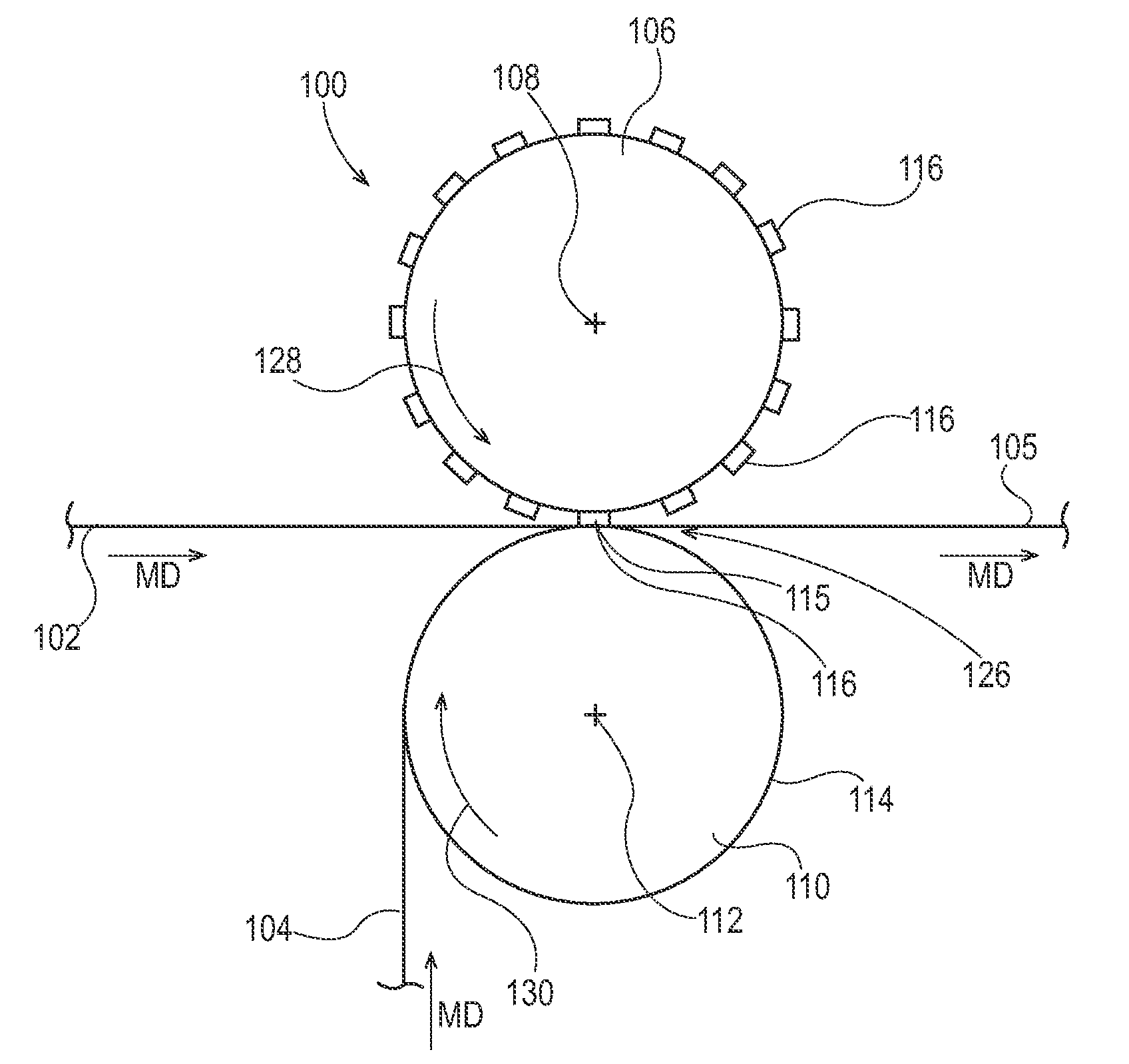
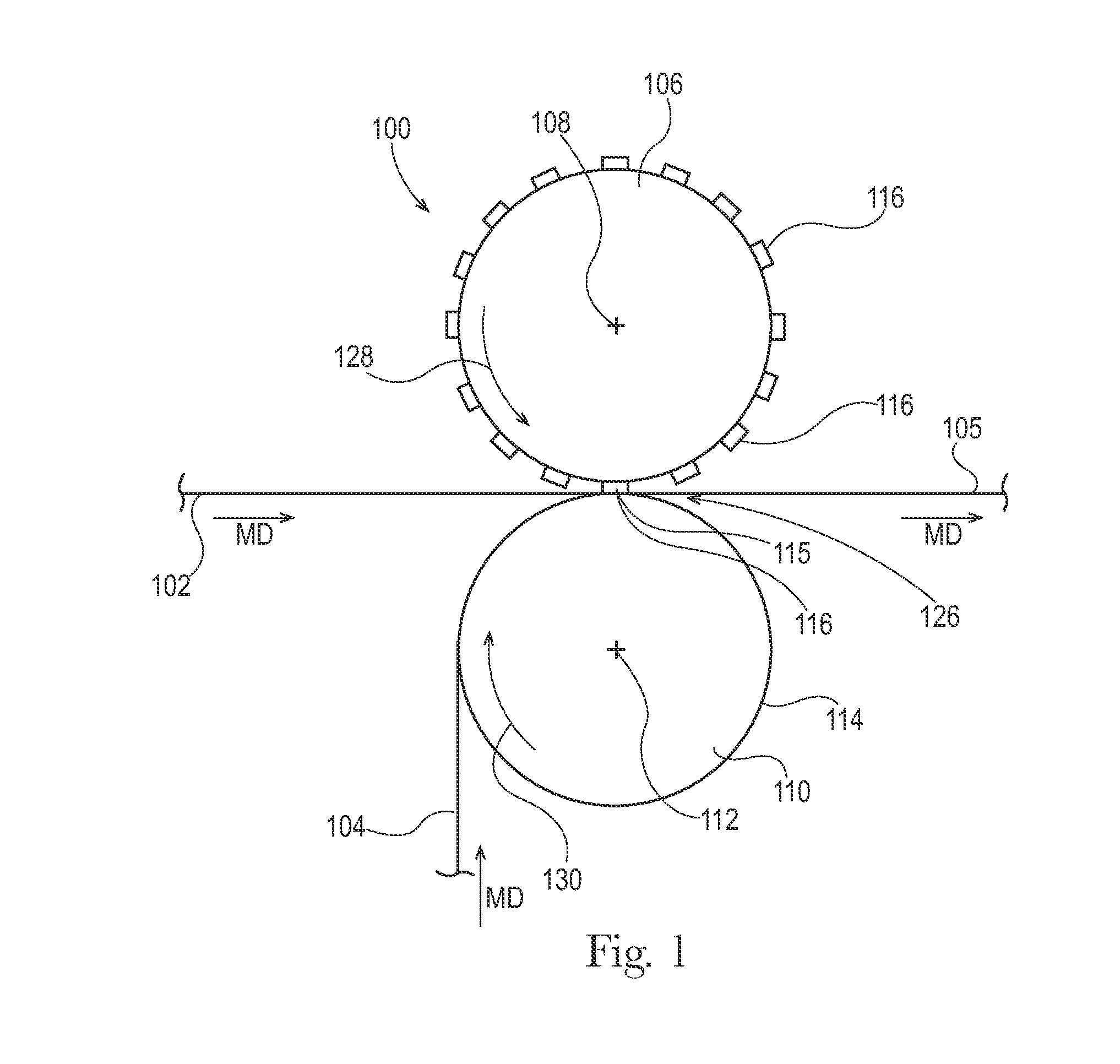
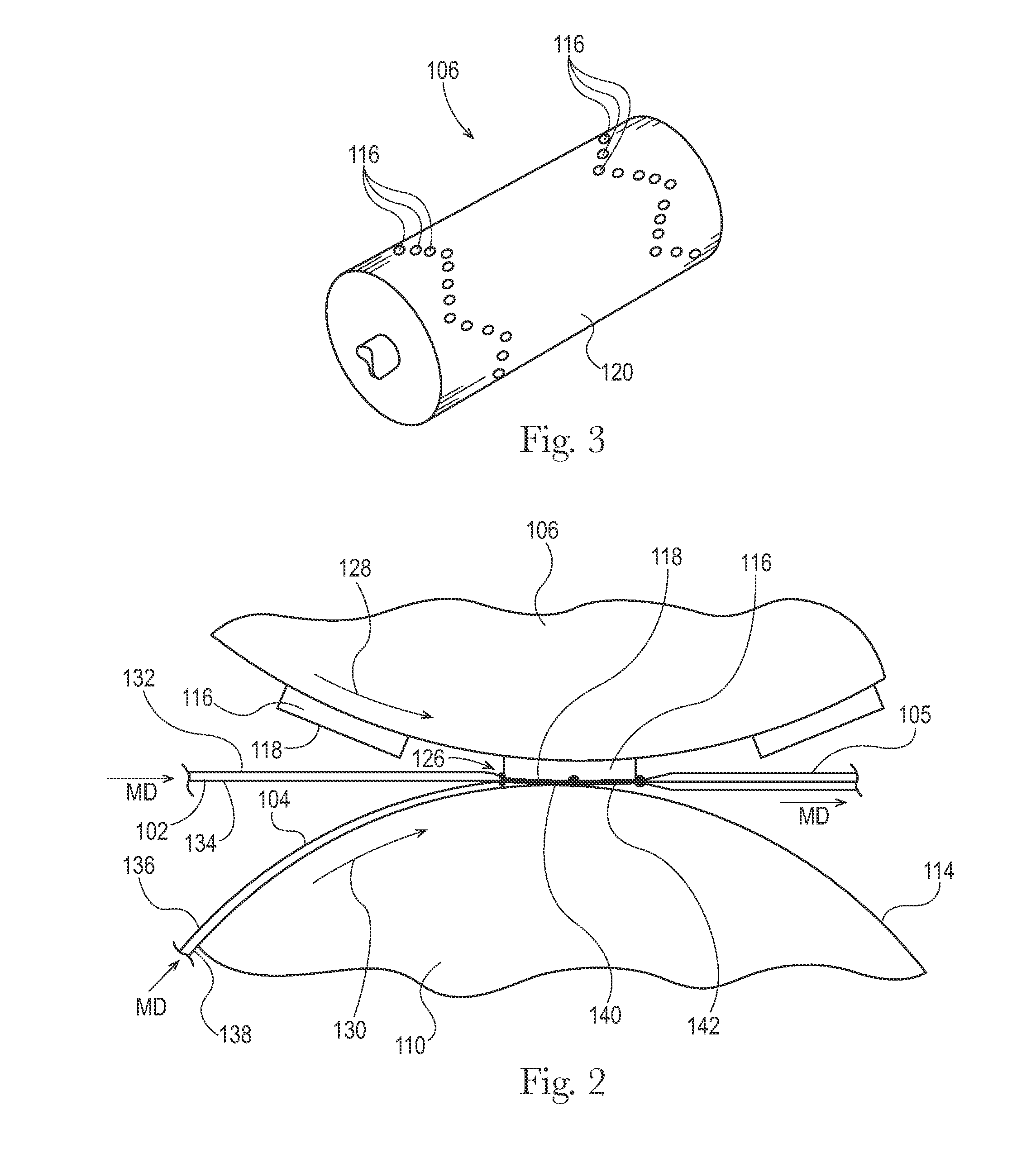
This patent is about methods and apparatuses for bonding substrates together through a pattern roll and an anvil roll. A pattern roll has a pattern surface with channels underneath it. As substrates pass between the pattern roll and anvil roll, they are compressed to form discrete bond regions between them. The process also forms a channel grommet region where some material flows from under the pattern surface into the channel. The invention also includes an apparatus for dynamically bonding substrates, where there is a nip pressure between the pattern surface and the anvil roll. Additionally, the patent describes a laminate with a discrete bond that has different basis weights and ratios in different regions. The technical effects of this invention include improved bonding efficiency and strength, as well as the ability to dynamically bond substrates.

Problems solved by technology

However, extreme nip pressures may exceed the compressive yield strength of cold work powder metal tool steels.
In addition, current mechanical bonding methods are susceptible to pattern element chipping, spalling, buckling, and / or otherwise fracturing, referred to generally as bond tool breakdown, sometimes necessitating frequent and costly repairs.
These mechanical bonding methods may also damage the laminae by forming holes and / or tears in or around the bond sites.
For example, pattern elements may become deformed and / or fail after prolonged use due to high stresses that occur in the center portions of the pattern element during the bonding operation.
In some instances, such high stresses may cause craters to form in the bonding surfaces of pattern elements.
As a pattern element degrades, the bonds created thereby may have inconsistent aesthetic appearances; have relatively weaker strengths; and may tear or cut the bonded laminae in areas adjacent to the bonds.
In addition, as the web basis weight of laminae decreases, bonds may become more susceptible to bond defects such as tearing and pinholes at relatively high nip pressures.

Method used


Image

  • Bonding Apparatus and Method
  • Bonding Apparatus and Method
  • Bonding Apparatus and Method

Examples


Embodiment Construction

[0044]The following term explanations may be useful in understanding the present disclosure:

[0045]“Absorbent article” is used herein to refer to consumer products whose primary function is to absorb and retain soils and wastes. “Diaper” is used herein to refer to an absorbent article generally worn by infants and incontinent persons about the lower torso. The term “disposable” is used herein to describe absorbent articles which generally are not intended to be laundered or otherwise restored or reused as an absorbent article (e.g., they are intended to be discarded after a single use and may also be configured to be recycled, composted or otherwise disposed of in an environmentally compatible manner).

[0046]An “elastic,”“elastomer” or “elastomeric” refers to materials exhibiting elastic properties, which include any material that upon application of a force to its relaxed, initial length can stretch or elongate to an elongated length more than 10% greater than its initial length and ...


PUM

PropertyMeasurementUnit
areasaaaaaaaaaa
widthaaaaaaaaaa
depthaaaaaaaaaa

Abstract

The present disclosure relates to methods and apparatuses for mechanically bonding substrates together. The apparatuses may include a pattern roll including a pattern element protruding radially outward. The pattern element includes a pattern surface and includes one or more channels adjacent the pattern surface. The pattern roll may be positioned adjacent an anvil roll to define a nip between the pattern surface and the anvil roll, wherein the pattern roll is biased toward the anvil roll to define a nip pressure between pattern surface and the anvil roll. As substrates advance between the pattern roll and anvil roll, the substrates are compressed between the anvil roll and the pattern surface to form a discrete bond region between the first and second substrates. As such, during the bonding process, some yielded substrate material flows from under the pattern surface and into the channel to form a channel grommet region.

Description

CROSS REFERENCE TO RELATED APPLICATIONS[0001]This application claims the benefit of U.S. Provisional Application 61 / 836,690, filed Jun. 19, 2013, which is hereby incorporated by reference.FIELD OF THE INVENTION[0002]The present disclosure relates to methods for manufacturing absorbent articles, and more particularly, to apparatuses and methods for bonding substrates that may be used as components of absorbent articles.BACKGROUND OF THE INVENTION[0003]Along an assembly line, various types of articles, such as for example, diapers and other absorbent articles, may be assembled by adding components to and / or otherwise modifying an advancing, continuous web of material. For example, in some processes, advancing webs of material are combined with other advancing webs of material. In other examples, individual components created from advancing webs of material are combined with advancing webs of material, which in turn, are then combined with other advancing webs of material. In some case...

Claims


Application Information

Patent Timeline
Patent Type & Authority Applications(United States)
IPC IPC(8): A61F13/15A61F13/514A61F13/49
CPCA61F13/15585A61F13/15731A61F13/15699A61F2013/15991A61F13/49011A61F13/51478A61F13/15577A61F13/15707B29C66/21B29C66/83411B29L2031/4878B29C65/18B29C65/8223B29C66/1122B29C66/22B29C66/342B29C66/346B29C66/43B29C66/729B29C66/81423B29C66/81429B29C66/83415B29C66/83511B29C66/929B29C65/02B29C65/56B29C66/232B29C66/71B29C66/72343Y10T428/24521B29K2023/00B29K2023/06B29K2023/12B29K2067/00B29K2077/00B31F2201/0733B29C66/81433B31F2201/0738
Inventor ECKSTEIN, JOSEPH ALLENBAO, HAILINGDREISIG, ROBERT CHARLESKALNITZ, HOWARD JAYSCHNEIDER, UWE
Owner THE PROCTER & GAMBLE COMPANY
Learn More