
IP multicast layered distribution method and system

Inactive Publication Date: 2014-12-25
PEKING UNIV SHENZHEN GRADUATE SCHOOL +2
View PDF0 Cites 31 Cited by
  • Summary
  • Abstract
  • Description
  • Claims
  • Application Information

AI Technical Summary

Benefits of technology

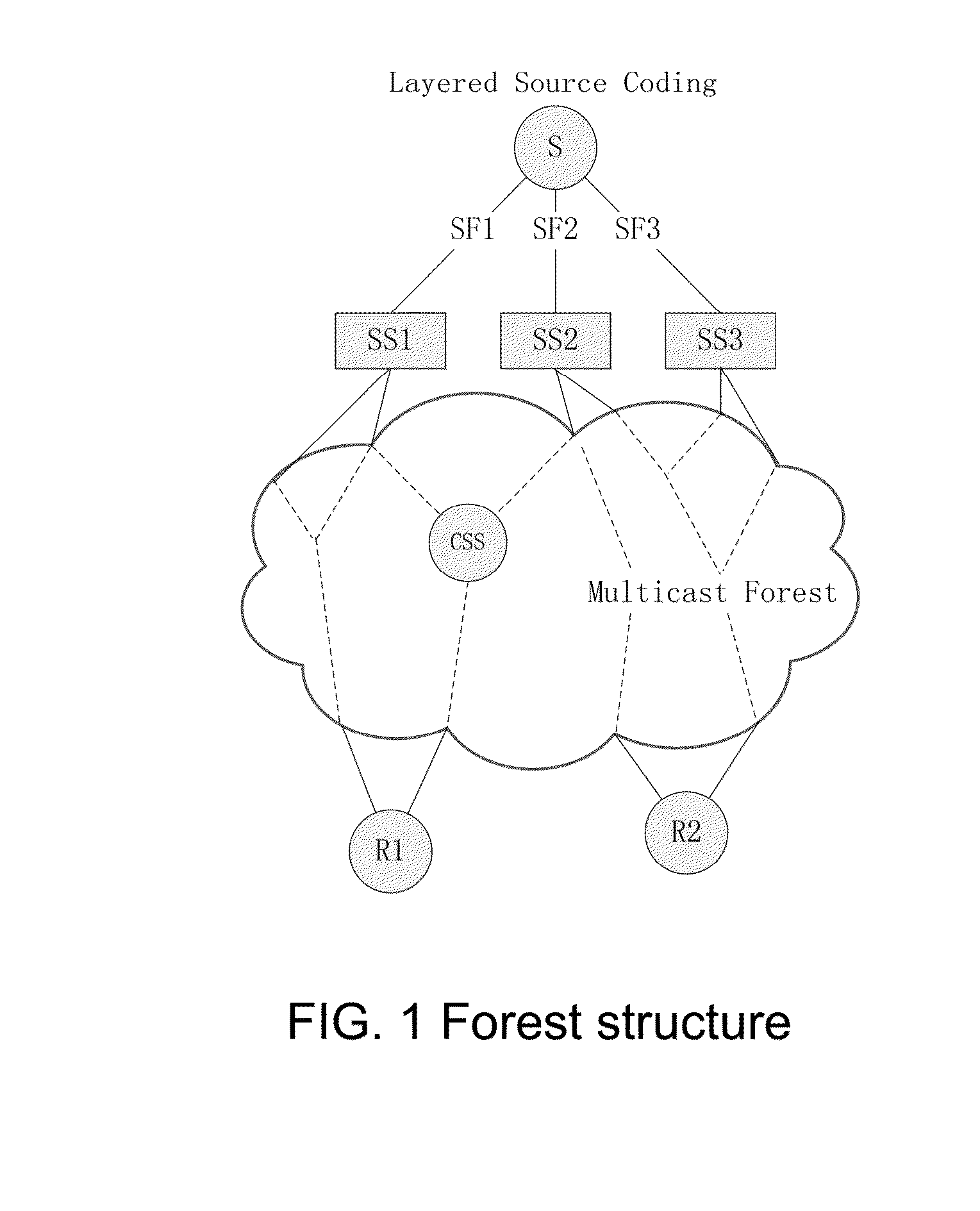
The present invention provides a method for efficiently distributing multicast data to multiple destinations using a shunt structure. The invention separates and recodes the original multicast data into multiple sub-flows through a source router, specifies different shunt sub-source and distributes sub-group address for each sub-flow. The invention creates a multicast data distribution structure in which each shunt sub-source transmits data to the new leaf node of each sub-tree and an intermediate node determined based on the reception of join news port. The invention also creates a multicast forest structure composed of each multicast distribution tree and each sub-flow. The use of the multicast forest structure parallel transmits sub-flows to different sinks, providing higher bandwidth and better stability than traditional multicast trees. The invention also provides better quality of service and support for isomerism users, expanding the application scope of traditional multicast.

Problems solved by technology

When the network have multiple receivers, unicast will lead to the same information with multiple copies in IP network, and repeat occupy network resources and server resources, so the transmission efficiency is low.
But broadcast has no way to cover different subnet, otherwise will cause broadcast storm.
However the traditional multicast transmission system structure still cannot get large-scale commercial deployment after 30 years development, the main reason is the current multicast structure performance is unstable, bandwidth lesser, the quality of service QoS difficult to guarantee, lack of effective certification charging mechanism, unable to provide differential service for heterogeneous sink and so on.
Network coding was born more than ten years so far, although many theoretical derivation and simulation verification try to prove that NC multicast can bring performance improvement, but still isn't applied in any practical multicast protocol.
The combination of Network coding and multicast do not enough in this regard.
Because in the multicast frame, there is no design effective group management strategy, and multicast routing algorithm is difficult to operate.
So, it can be said that the NC multicast model cannot support the dynamic Join / Prune operation, thus could not be practical.
In the current technology, usually adopting centralized algorithm code subgraph structure, which does not support composition members to join and leave dynamically.
These network coding schemes are difficult to practical for the pursuit of good theoretical performance leads to ignore the actual network conditions and management details.
In conclusion, the existing technology solutions can't effectively support group dynamic join / leave, and throughput and transmission performance is low and can't provide a hierarchical QOS guarantee to support user isomerism.

Method used


Image

  • IP multicast layered distribution method and system
  • IP multicast layered distribution method and system
  • IP multicast layered distribution method and system

Examples


implementation example 1

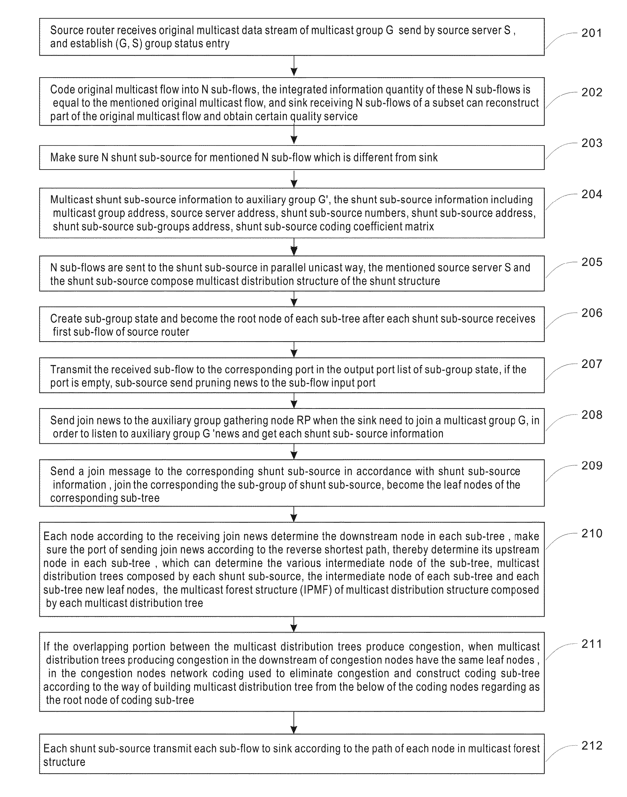
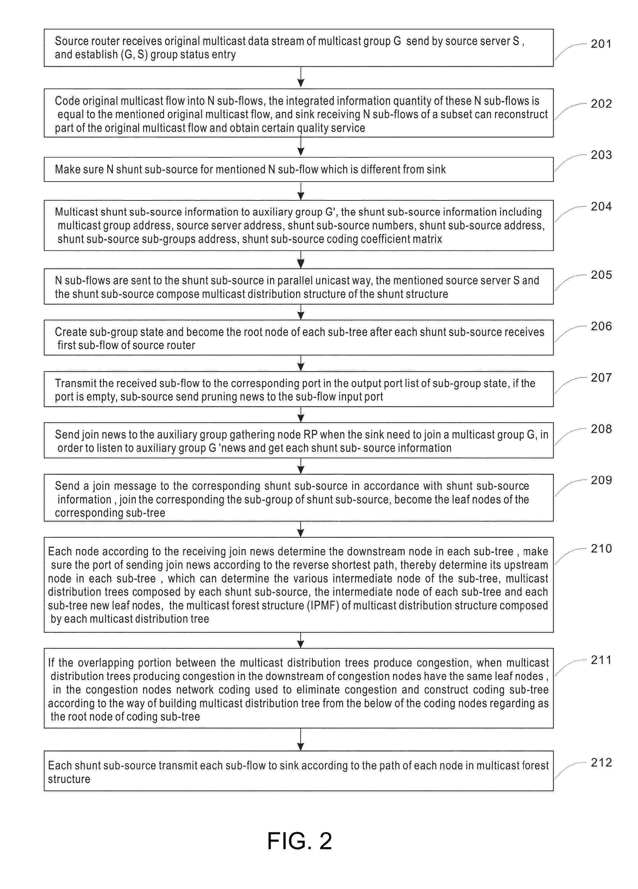
[0092]From the FIG. 2, we can know the implementing process of the present invention example 1 for IP multicast data layer distribution method. The method can be applied to IP multicast data layer distribution system including source server, source router, sub-source, intermediate node and sink. Here the intermediate node is located in the route between sub-source and sink, details as follows:

[0093]201. Source router receives original multicast data stream of multicast group G send by source server S, and establish (G, S) group status entry.

[0094]In this example, the active source server S, generates a original multicast data flow at rate of 2 multicast group G, and the flow is sent to the adjacent source router. Source router create group status entry (G, S) for the group G and the source server S, and set the input port receiving the original multicast data stream to incoming interface for (G, S).

[0095]202. Code original multicast flow into N sub-flows, the integrated information ...

implementation example 2

[0131]The present invention implementation example 2 shows the realization process of IP multicast layer distribution method that is same with the example 1. The difference between them is that, in this example, when the sub-flow passing into the two sub-source collide, some intermediate node become coding sub-source. The implementation case mainly detailed after sink according to the mentioned shunt sub-source send join news to the corresponding shunt sub-source send, when the two sub-flow receiving news occur a collision, the above two sub-flow are made network code, and then how to determine the intermediate nodes between the source server and sink, as detailed below:

[0132]If different join news sent by sink to different shunt sub-source through the same link reach the intersection node, and the above two sub-flow sum of bandwidth is greater than the effective bandwidth of the stated output port, thus turn on the intersection node's coding sub-source function, make the above two ...

implementation example 3

[0190]FIG. 5 shows the IP multicast data layer distribution system structure diagram about the example 3. It only shows the relevant sections of the example. The system includes source server S, source router DR, shunt son sub-source SS1 and SS2, intermediate node (D, E and C) and sink R.

[0191]The source router include:

[0192]Set of state build unit, used for receiving the multicast group G original multicast flow sent by the source server S and establishing the (G, S) group state.

[0193]Sub-flow generation unit, used for coding original multicast flow for N sub-flows, the integrated information quantity of these N sub-flows is equal to the mentioned original multicast flow, and sink receiving N sub-flows of a subset can reconstruct part of the original multicast flow and obtain certain quality service.

[0194]Shunt sub-source determining unit, used for making sure N shunt sub-source for mentioned N sub-flow which is different from sink.

[0195]Sub-source multicast unit, used to multicast...


PUM


Abstract

The present invention relates to IP network communication technology. It provides a kind of IP multicast data layer distribution method and system. The method includes: first code original multicast data into multiple sub-flow, separately specify different shunt sub-source for every sub-flow, distribute sub-group address, create sub-group state, etc, form shunt structure. Then the sink send join news to each shunt sub-source, join each shunt sub-source sub-group and become the leaf node of each sub-tree. And then each shunt sub-source determine the intermediate node according to the port receiving join news and construct multicast distribution-tree. If the overlapping portion between the multicast distribution trees produce congestion, in the congestion nodes network coding is used to eliminate congestion and construct coding sub-tree according to the way of building multicast distribution tree from the below of the coding nodes.

Description

FIELD OF THE INVENTION[0001]The invention relates to the IP network communication technology, especially relates to an IP multicast hierarchical distributed method and system.BACKGROUND OF THE INVENTION[0002]A kind of IP network communication is unicast, its characteristic is once the transmission of a message to a receiver; Another is broadcast, which transmit a message to all receivers once in the subnet. When the network have multiple receivers, unicast will lead to the same information with multiple copies in IP network, and repeat occupy network resources and server resources, so the transmission efficiency is low. But broadcast has no way to cover different subnet, otherwise will cause broadcast storm. Therefore, multicast transmission that is “transmitting a message to multiple receiver once” comes into being.[0003]PIM-SM protocol namely Protocol Independent Multicast-Sparse Mode. PIM-SM protocol is the current recognition IP layer multicast protocols. The characteristic of P...

Claims


Application Information

Patent Timeline
IPC IPC(8): H04L12/18H04L12/24H04L12/44H04L12/721H04L45/16
CPCH04L12/1886H04L12/185H04L12/44H04L41/12H04L45/124H04L45/16H04L47/12H04L12/1877
Inventor LI, HUILI, YININGCHEN, CHANGMINZHOU, JINGBANGZHANG, HUAYUFENG, JUNQIUZHANG, YUMENGHOU, HANXUGUO, HANAN, HUIYAO
Owner PEKING UNIV SHENZHEN GRADUATE SCHOOL
Learn More