Subject information obtaining apparatus
a subject information and apparatus technology, applied in applications, ultrasonic/sonic/infrasonic image/data processing, tomography, etc., can solve problems such as the s/n ratio may decrease, and achieve the effect of improving the s/n ratio and suppressing the attenuation of an acoustic wav
- Summary
- Abstract
- Description
- Claims
- Application Information
AI Technical Summary
Benefits of technology
Problems solved by technology
Method used
Image


Examples
first exemplary embodiment
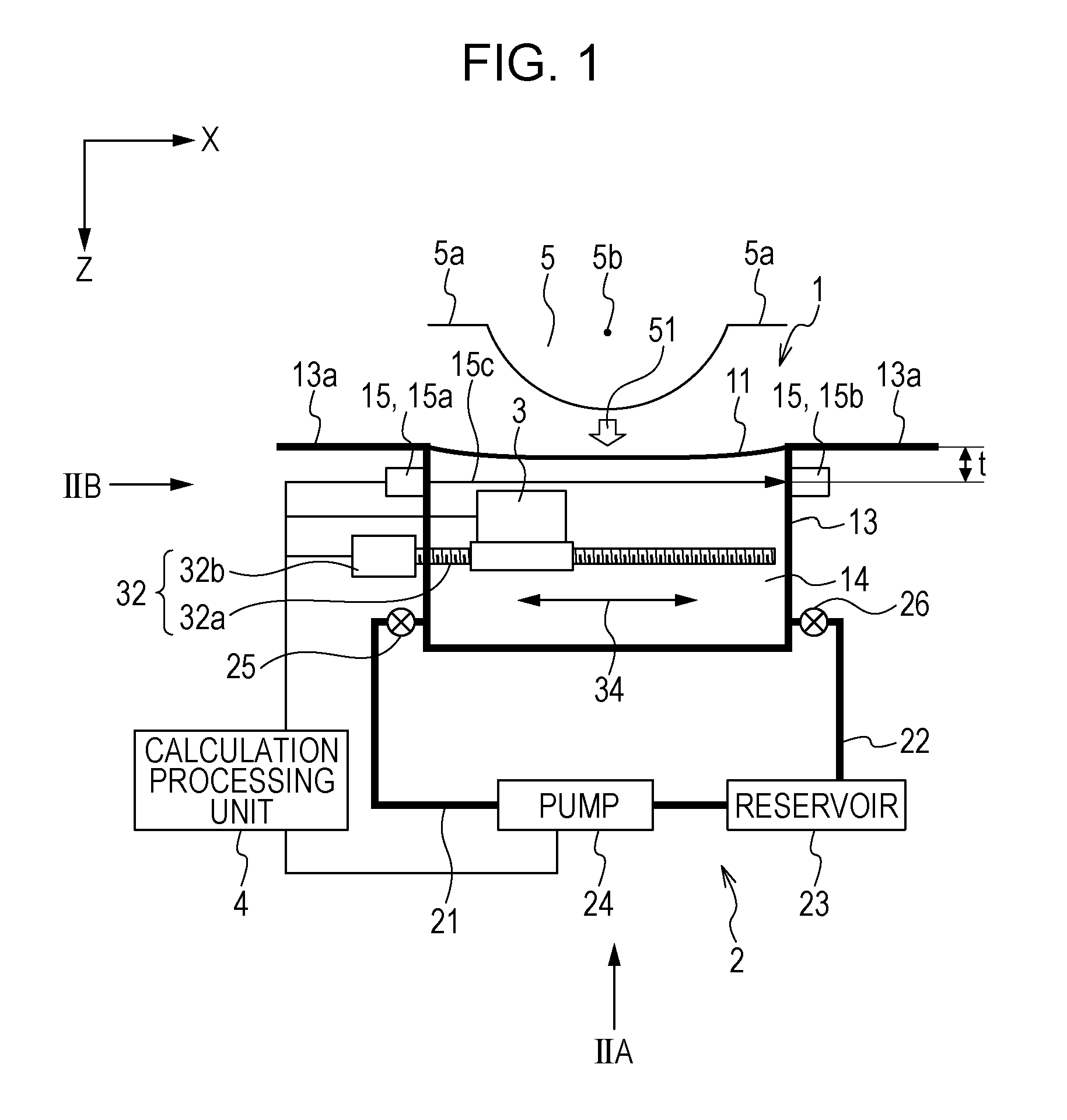
[0028]FIG. 1 schematically illustrates an exemplary configuration of a subject information obtaining apparatus according to a first exemplary embodiment.
[0029]A holding unit 1 has a watertight structure formed by the holding member 11 that holds the subject 5 and a receptacle 13, and the holding member 11 and the receptacle 13 form a sealed container. The holding member 11 is preferably formed by a member having an acoustic impedance (1.5 to 1.6×10⁶ kg / m2sec) that is substantially the same as the acoustic impedance of the subject 5 or the probe 31, which will be described later, and in the case of an apparatus that utilizes photoacoustic effects, the holding member 11 is preferably formed by a member having high light transmittance (preferably, 90% or higher). Specific materials that match the above description include silicone rubber, urethane rubber, styrene-based elastomer, and olefin-based elastomer. A flexible material, such as rubber, has an advantage in that such a material i...
second exemplary embodiment
[0049]In a second exemplary embodiment, part of the receptacle is formed by a deformable member, and the shape of the holding member 11 is controlled by changing the shape of the deformable member. Configurations that are identical to those of the first exemplary embodiment will be given identical reference characters, and descriptions thereof will be omitted.
[0050]FIGS. 7A and 7B schematically illustrate an exemplary configuration of a subject information obtaining apparatus according to the second exemplary embodiment. FIG. 7A illustrates the holding member 11 before the shape thereof is controlled, and FIG. 7B illustrates the holding member 11 after the shape thereof has been controlled. A receptacle is formed by a frame 61 and a deformable member 62 serving as a base. The frame 61 and the deformable member 62 form a watertight structure that can sealingly hold the acoustic matching liquid 14 thereinside. In addition, as in the receptacle 13 of the first exemplary embodiment, the...
third exemplary embodiment
[0054]In a third exemplary embodiment, the shape of the holder is detected in a direction parallel to the direction along which the directivity of the receiver is high, and thus a distance measuring sensor is provided to serve as the shape detector for the holding member 11. FIG. 8A schematically illustrates a configuration of a subject information obtaining apparatus according to the third exemplary embodiment. FIG. 8B schematically illustrates the configuration of the subject information obtaining apparatus according to the third exemplary embodiment, as viewed from a side at which the holding member 11 is provided. A distance measuring sensor 16 is provided on the base of the receptacle 13 so as to measure the distance between the distance measuring sensor 16 and the holding member 11. An ultrasonic sensor, for example, can be used as the distance measuring sensor 16. The probe unit 3 is moved by a scanning mechanism 37 that is capable of moving the probe unit 3 along two axes wi...
PUM
 Abstract
Description
Claims
Application Information
 - R&D
- Intellectual Property
- Life Sciences
- Materials
- Tech Scout
- Unparalleled Data Quality
- Higher Quality Content
- 60% Fewer Hallucinations
Browse by: Latest US Patents, China's latest patents, Technical Efficacy Thesaurus, Application Domain, Technology Topic, Popular Technical Reports.
© 2025 PatSnap. All rights reserved.Legal|Privacy policy|Modern Slavery Act Transparency Statement|Sitemap|About US| Contact US: help@patsnap.com