Magnetic coupling type isolator

a type of isolator and magnetic coupling technology, applied in the field of magnetic coupling type isolators, can solve the problems of inability to obtain a sufficient tolerance to external magnetic fields or ems, and achieve the effect of suppressing attenuation in the magnetic field

Inactive Publication Date: 2013-05-07
ALPS ALPINE CO LTD
View PDF5 Cites 3 Cited by
  • Summary
  • Abstract
  • Description
  • Claims
  • Application Information

AI Technical Summary

Benefits of technology

[0011]In this configuration, since the first and second shield films are overlapped with the magnetic field generator and the magnetoresistive element as seen in a top plan view, it is possible to obtain a sufficient tolerance to an external magnetic field or an EMS. Since the distance between the magnetoresistive element and the second shield film is set to 8 to 100 μm, it is possible to suppress attenuation in the magnetic field applied from the magnetic field generator to the magnetoresistive element.
[0013]In the magnetic coupling type isolator according to an embodiment of the present invention, it is preferable that the first shield film has a function of enhancing the magnetic field applied from the magnetic field generator to the bridge circuit.
[0016]A magnetic coupling type isolator according to the embodiment of the present invention includes a magnetic field generator for generating an external magnetic field by an input signal, a magnetoresistive element for detecting the external magnetic field and converting the detected magnetic field into an electric signal, the magnetoresistive element being electrically insulated from the magnetic field generator and positioned in a location capable of being magnetically coupled so as to be overlapped with the magnetic field generator as seen in a top plan view, and first and second shield films overlapped with the magnetic field generator and the magnetoresistive element as seen in a top plan view, wherein a distance between the magnetoresistive element and the second shield film is set to 8 to 100 μm. Accordingly, it is possible to suppress attenuation in the magnetic field applied from the magnetic field generator to the magnetoresistive element.

Problems solved by technology

Therefore, it may be impossible to obtain a sufficient tolerance to the external magnetic fields or an EMS (electro magnetic susceptibility).

Method used


Image

  • Magnetic coupling type isolator
  • Magnetic coupling type isolator
  • Magnetic coupling type isolator

Examples


Embodiment Construction

[0026]Hereinafter, embodiments of the invention will be described in detail with reference to the accompanying drawings.

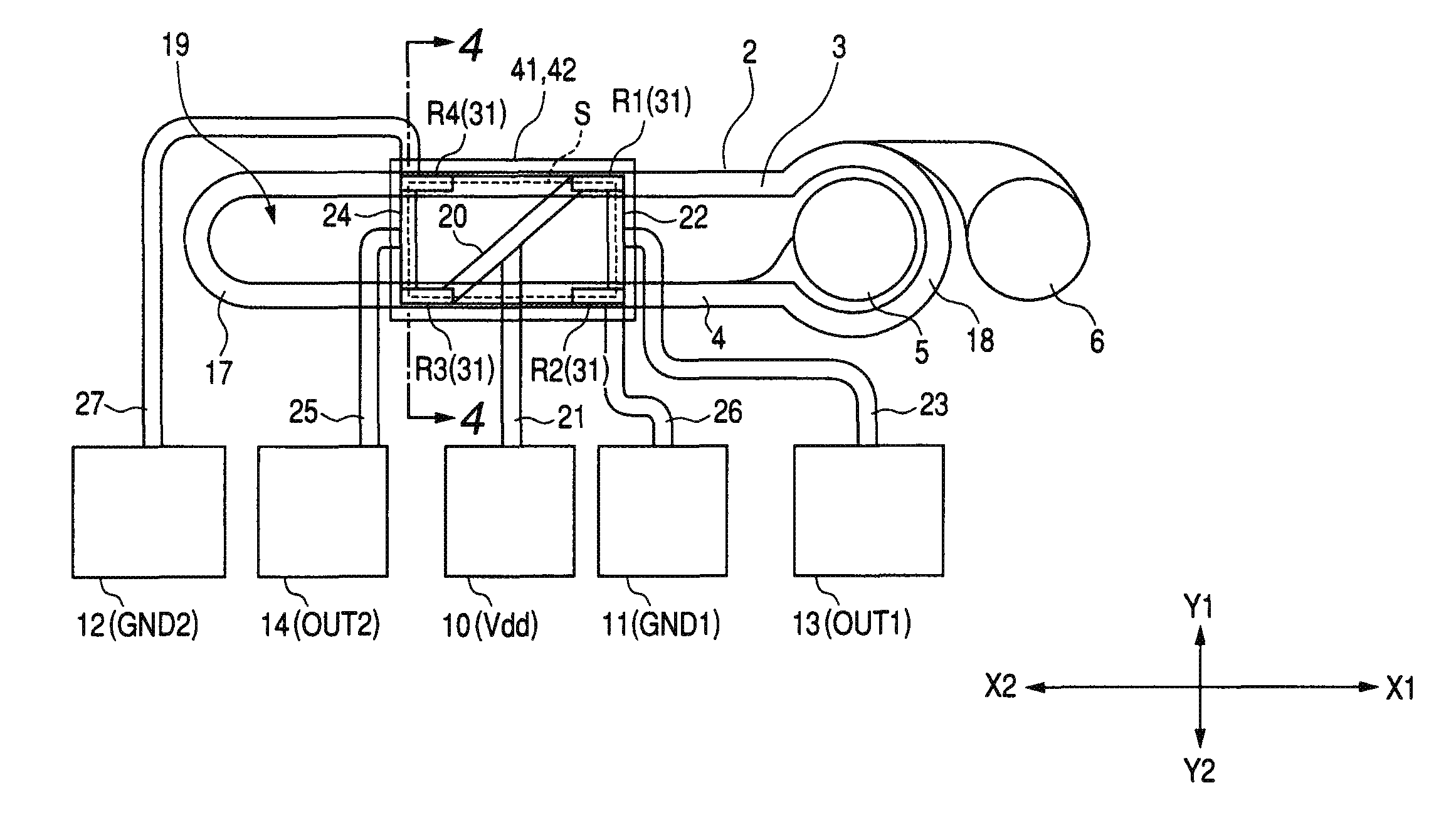
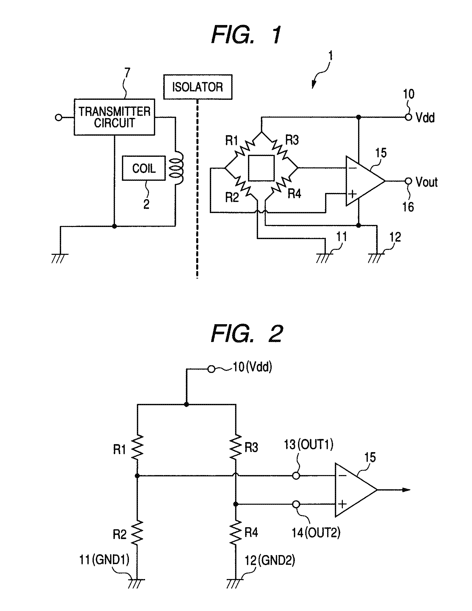
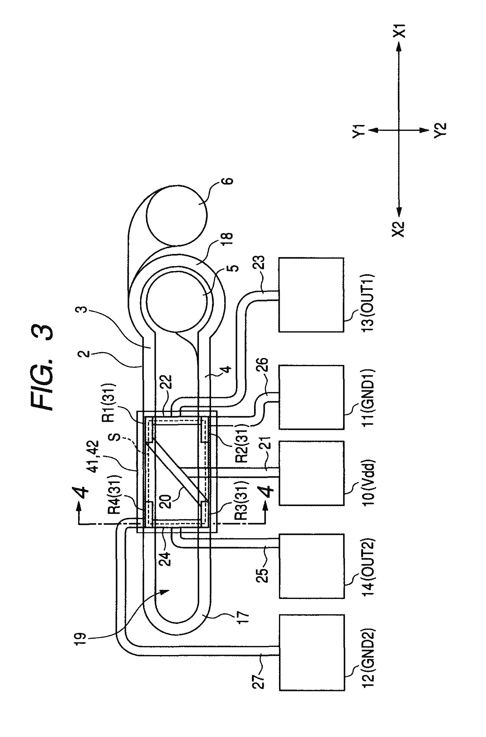
[0027]FIG. 1 is a circuit diagram illustrating an entire configuration of a magnetic coupling type isolator (or magnetic coupler) according to an embodiment of the invention. FIG. 2 is a circuit diagram illustrating a bridge circuit including magnetoresistive elements R1 to R4. FIG. 3 is a partial plan diagram illustrating a magnetic coupling type isolator according to an embodiment of the invention. FIG. 4 is a partially cross-sectional diagram viewed from an arrow direction and cut away in a thickness direction along a line A-A of FIG. 3. In addition, while the insulation layer is not shown, and only the inner and outer edges of the coil 2 are shown in FIG. 3, the magnetoresistive elements R1 to R4 underlying the coil 2 are shown by transparency.

[0028]As shown in FIG. 1, the magnetic coupling type isolator 1 includes a coil 2 as a magnetic field generator for gen...


PUM

PropertyMeasurementUnit
distanceaaaaaaaaaa
thicknessaaaaaaaaaa
external magnetic fieldaaaaaaaaaa

Abstract

A magnetic coupling type isolator includes: a magnetic field generator for generating an external magnetic field by an input signal; a magnetoresistive element for detecting the external magnetic field and converting the detected magnetic field into an electric signal, the magnetoresistive element being electrically insulated from the magnetic field generator and positioned in a location capable of being magnetically coupled so as to be overlapped with the magnetic field generator as seen in a top plan view; and first and second shield films overlapped with the magnetic field generator and the magnetoresistive element as seen in a top plan view, wherein a distance between the magnetoresistive element and the second shield film is set to 8 to 100 μm.

Description

CROSS REFERENCE TO RELATED APPLICATION[0001]The present invention contains subject matter related to Japanese Patent Application JP 2009-109610 filed in the Japanese Patent Office on Apr. 28, 2009, the entire contents of which being incorporated herein by reference.BACKGROUND[0002]1. Technical Field[0003]The present invention relates to a magnetic coupling type isolator having a magnetic field generator and a magnetoresistive element such as a TMR (tunneling magnetoresistance) element, a CIP-GMR (current-in-plane giant magnetoresistance) element, and CPP-GMR (current perpendicular-to-the-plane) element.[0004]2. Related Art[0005]In an electronic circuit, for example, if a portion where a large current flows and a portion where a signal is transmitted are approximated to each other, the portion where a large current flows may influence signal transmission. For this reason, a circuit element for electrically separating the portion where a large current flows from the portion where a si...

Claims


Application Information

Patent Timeline
Patent Type & Authority Patents(United States)
IPC IPC(8): G11B5/39
CPCG01R33/098
Inventor IDE, YOSUKESAITO, MASAMICHITAKAHASHI, AKIRANOJIMA, TSUYOSHINISHIYAMA, YOSHIHIROKOBAYASHI, HIDEKAZUICHINOHE, KENJISAKATSUME, NAOKI
Owner ALPS ALPINE CO LTD
Why Eureka
Try Eureka