Bow
- Summary
- Abstract
- Description
- Claims
- Application Information
AI Technical Summary
Benefits of technology
Problems solved by technology
Method used
Image


Examples
first embodiment
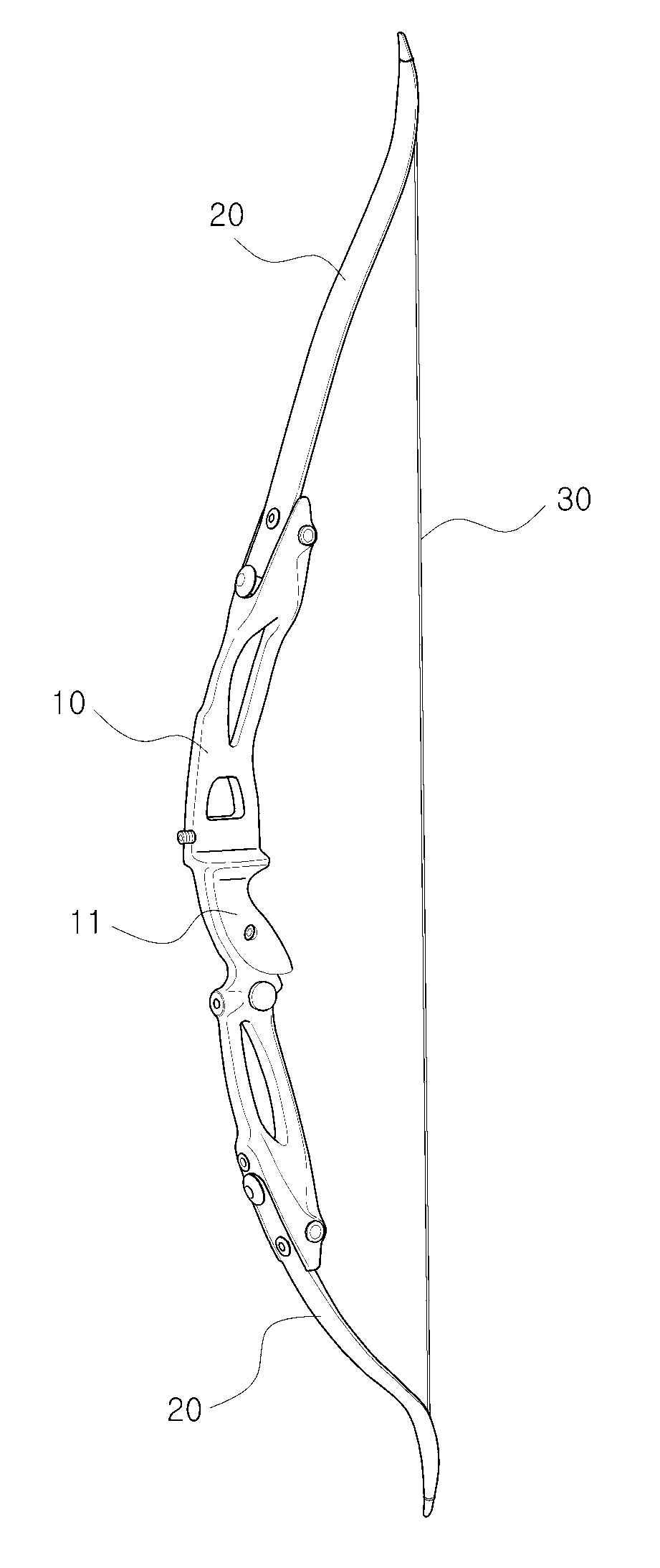
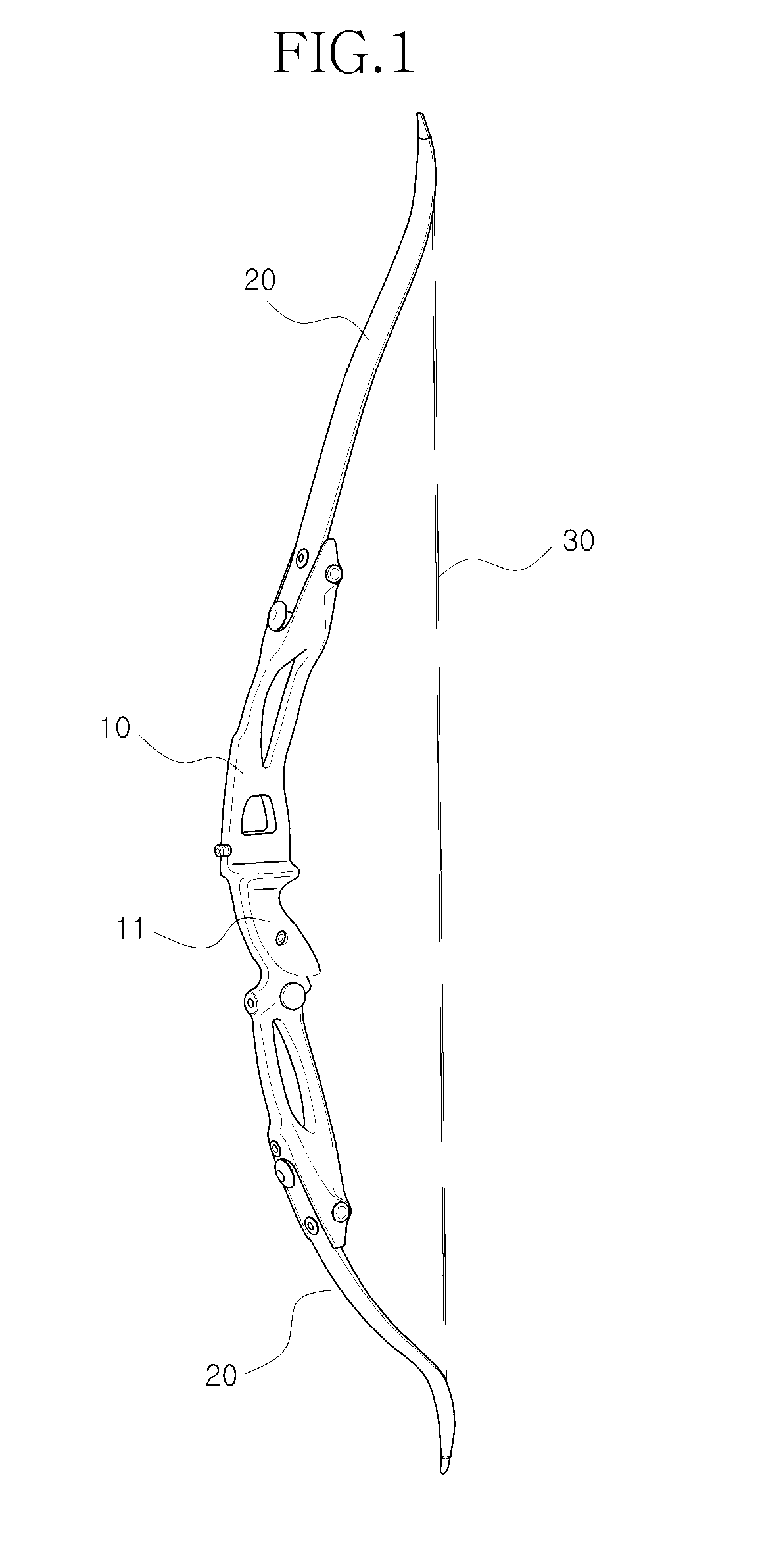
[0027]As illustrated, the bow according to the present invention includes: a handle 100 at a central portion of which a grip portion 11 of FIG. 1 is formed in which the grip portion 11 is gripped by a user; a pair of wings 200 that are respectively coupled to both ends of the handle 100; and a bow string that is tied between the pair of the wings 200. Here, a coupling pin 220 is formed in a rear side of one end of each wing 200 coupled to the handle 100, and a fitting groove 210 is formed at one end of each wing 200. In addition, a coupling groove 130 into which the coupling pin 220 of each wing 200 is coupled is formed at one end of the handle 100 to which each wing 200 is coupled, and a fixing pin 120 that is inserted into the fitting groove 210 of each wing 200 is formed at the one end of the handle 100 to which each wing 200 is coupled. In addition, a buffer pin member 300 that is configured to include a pin member 310 that is inserted into an insertion hole 230 formed in each w...
third embodiment
[0042]A buffer pin member 500 in the third embodiment includes a pin member 510 that is inserted into an insertion hole 150 of the handle 100 and coupled to each wing 200, and a first cushioning member 530 that is formed between a rear end 520 of the pin member 510 and the handle 100.
[0043]In the third embodiment, the pin member 510 of the buffer pin member 500 is inserted into the insertion hole 150 of the handle 100 at the rear side of the handle 100, to then be coupled to each wing 200, and a rear end 520 of the pin member 510 is disposed at the rear side of the handle 100. The pin member 510 is detachably screwed with each wing 200 between the coupling groove 130 and the fixing pin 120.
[0044]A first cushioning member 530 is coupled to the pin member 510 between the rear end 520 of the pin member 510 and the handle 100, and the material of the first cushioning member 530 is made in the same manner as that of the first embodiment.
[0045]In the third embodiment, when the pin member ...
fourth embodiment
[0048]In the fourth embodiment, instead of the buffer pin member in the previous embodiments, a front support portion 170 is formed at one end of the handle 100 coupled to each wing 200 and a cushioning member 600 is provided between the front supporting portion 170 and each wing 200.
[0049]In this embodiment, the front support portion 170 is bent in an L-shaped form at both sides 160 of the handle 100 that is located at both sides of each wing 200, and is located in front of each wing 200. In addition, the front support portion 170 is formed to have a predetermined length in the longitudinal direction. In addition, the cushioning member 600 having the same length as that of the front support portion 170 is combined between the front support portion 170 and each wing 200 on the rear surface of the front supporting portion 170. The material of the cushioning member 600 is the same as those of the previous embodiments.
[0050]Thus, even in the fourth embodiment, a configuration such as t...
PUM
 Abstract
Description
Claims
Application Information
 - R&D
- Intellectual Property
- Life Sciences
- Materials
- Tech Scout
- Unparalleled Data Quality
- Higher Quality Content
- 60% Fewer Hallucinations
Browse by: Latest US Patents, China's latest patents, Technical Efficacy Thesaurus, Application Domain, Technology Topic, Popular Technical Reports.
© 2025 PatSnap. All rights reserved.Legal|Privacy policy|Modern Slavery Act Transparency Statement|Sitemap|About US| Contact US: help@patsnap.com