
System and method for controlling ice formation on gas turbine inlet guide vanes

a technology of inlet guide vanes and control systems, which is applied in the direction of engine starters, instruments, optical radiation measurement, etc., can solve the problems of gas turbines ice formation risk, subsequent ice ingestion, ice formation on inlet guide vanes, etc., and achieve the effect of improving operating efficiency

Active Publication Date: 2014-12-04
SIEMENS ENERGY INC
View PDF6 Cites 12 Cited by
  • Summary
  • Abstract
  • Description
  • Claims
  • Application Information

AI Technical Summary

Benefits of technology

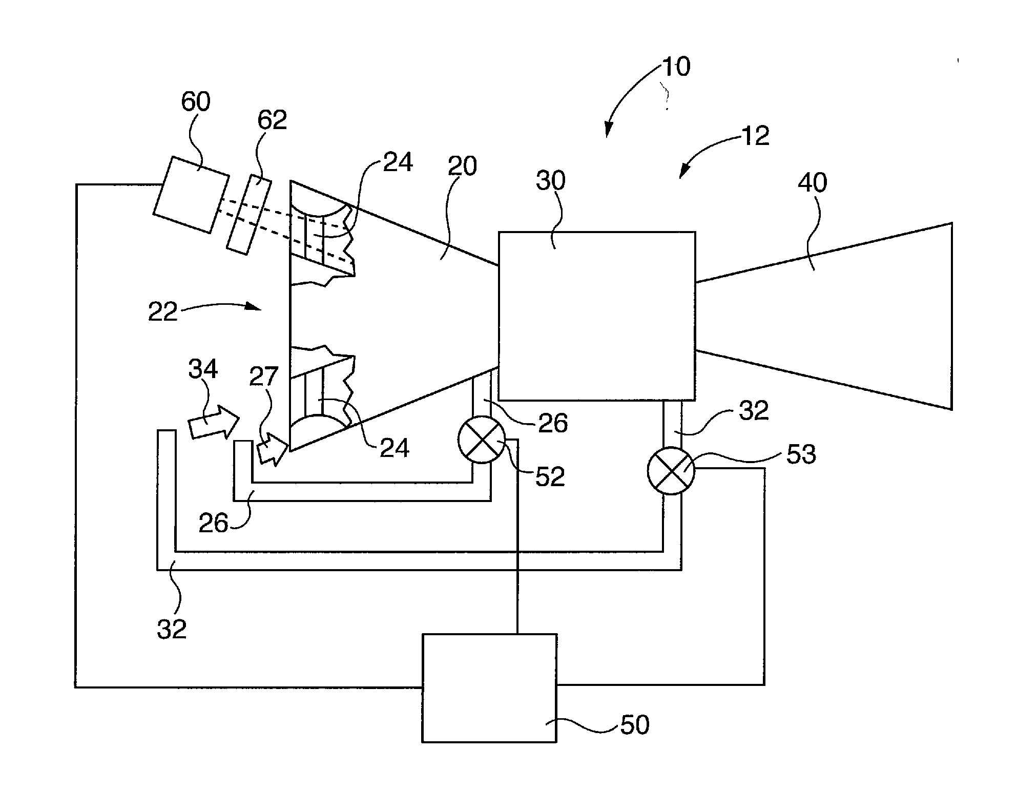
The invention creates a system to prevent ice formation on the inlet guide vanes of a gas turbine by using infra-red monitoring to detect and thaw the ice in real-time without the need for excessive air bleeds from the turbine. This reduces the amount of air needed and increases the efficiency of the turbine.

Problems solved by technology

Gas turbines risk ice formation on inlet guide vanes and subsequent ice ingestion when relative humidity and temperature properties of engine intake air within the turbine inlet drop its dew point below water freezing temperature.
Therefore, while ambient air temperature may be above the water freezing point, the combination of relative humidity and lower air temperature within the turbine intake may lead to ice formation on inlet guide vanes.
When ice breaks off an inlet guide vane it is ingested by the turbine, potentially causing damage to internal components such as blades and vanes.
It is desirable to minimize compressed or heated air bleeding as they lower gas turbine operating efficiency.
The added conservative safety margins further reduce turbine operating efficiency.

Method used


Image

  • System and method for controlling ice formation on gas turbine inlet guide vanes
  • System and method for controlling ice formation on gas turbine inlet guide vanes
  • System and method for controlling ice formation on gas turbine inlet guide vanes

Examples


Embodiment Construction

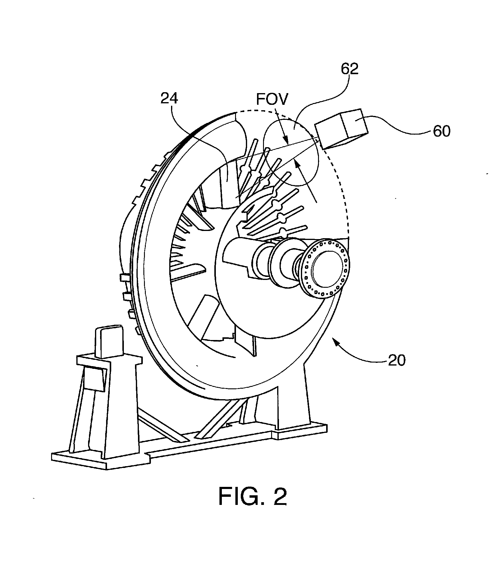
[0023]After considering the following description, those skilled in the art will clearly realize that the teachings of the present invention can be readily utilized in gas turbine inlet guide vane ice detection and control systems and methods that utilize active infra-red monitoring of inlet guide vanes, detection of ice formation on the guide vanes and elimination of the ice by altering properties of the gas turbine inlet intake airflow, such as by introducing compressed and / or heated air bled from the turbine. These systems and methods control ice formation by direct monitoring of inlet guide vane icing conditions, rather than by indirect empirical assumptions of ice formation based on atmospheric condition monitoring. Direct monitoring mitigates ice formation in real time without reliance on excessive use of gas turbine compressed or heated air bleeds operational safety margins that are frequently employed in the known indirect monitoring systems. Thus direct monitoring of icing ...


PUM


Abstract

Gas turbine inlet guide vane ice detection and control systems and methods that utilize active infra-red monitoring of inlet guide vanes, detection of ice formation on the guide vanes and elimination of the ice by altering properties of the gas turbine inlet intake airflow, such as by introducing compressed and / or heated air bled from the turbine. Ice has lower detectable emissivity intensity in the infra-red spectrum than ice-free inlet guide vane surfaces. Ice formation is inhibited by direct monitoring of inlet guide vane icing conditions, rather than by indirect empirical assumptions of ice formation based on atmospheric condition monitoring. Direct monitoring mitigates ice formation in real time without reliance on excessive use of gas turbine compressed or heated air bleed, which enhances turbine operational efficiency.

Description

BACKGROUND OF THE INVENTION[0001]1. Field of the Invention[0002]The invention relates to gas turbine inlet guide vane ice detection and control systems and methods. More particularly the invention utilizes active infra-red monitoring of inlet guide vanes, detection of ice formation on the guide vanes and elimination of the ice by altering properties of the gas turbine inlet intake airflow, such as by introducing compressed and / or heated air bled from the turbine.[0003]2. Description of the Prior Art[0004]Gas turbines risk ice formation on inlet guide vanes and subsequent ice ingestion when relative humidity and temperature properties of engine intake air within the turbine inlet drop its dew point below water freezing temperature. Intake air flows at sufficiently high velocity to lower its temperature below that of ambient air. Therefore, while ambient air temperature may be above the water freezing point, the combination of relative humidity and lower air temperature within the tur...

Claims


Application Information

Patent Timeline
IPC IPC(8): F01D25/02G01J5/00G01M15/14
CPCF01D25/02G01M15/14G01J5/0088F01D21/003F02C7/047F02C7/057F05D2260/80F05D2270/44F05D2270/804F05D2270/8041
Inventor HATCHER, JR., CLIFFORDRUHGE, FORREST R.
Owner SIEMENS ENERGY INC
Learn More