
Information processing apparatus, control method therefor, and computer-readable storage medium

a technology of information processing apparatus and control method, which is applied in the direction of closed circuit television system, television system, instruments, etc., can solve the problems of reducing the life of mercury lamps, affecting the stability of mercury lamps, and the need to suppress an increase in temperature, so as to shorten the on time of light sources, prevent an increase in light source temperature, and prolong life

Inactive Publication Date: 2014-12-04
CANON KK
View PDF2 Cites 26 Cited by
  • Summary
  • Abstract
  • Description
  • Claims
  • Application Information

AI Technical Summary

Benefits of technology

The present invention aims to solve the problem of light sources getting too hot and causing damage. It proposes a solution to make the light source last longer and save power. This is accomplished by shortening the time it takes for the light source to be fully on.

Problems solved by technology

Unfortunately, the above-mentioned related art techniques pose the following problem.
Unlike a halogen lamp, the mercury lamp uses no filaments, and therefore has a relatively long life, but requires component replacement every few months when it is always kept ON for the industrial purpose.
Also, it takes much time for the mercury lamp to become stable after turn-on, so the mercury lamp must be kept ON during the required process time once it is turned on.
This is disadvantageous in terms of not only wastefully keeping the mercury lamp ON during a time other than the measurement time, but also making it necessary to suppress an increase in temperature as the mercury lamp must be kept ON for a long time.
Furthermore, none of Japanese Patent Laid-Open No. 2009-186404, Japanese Patent No. 2997245, and Japanese Patent Laid-Open No. 7-234929 accurately control light emission within one frame in accordance with the projection and image capture characteristics.

Method used


Image

  • Information processing apparatus, control method therefor, and computer-readable storage medium
  • Information processing apparatus, control method therefor, and computer-readable storage medium
  • Information processing apparatus, control method therefor, and computer-readable storage medium

Examples


first embodiment

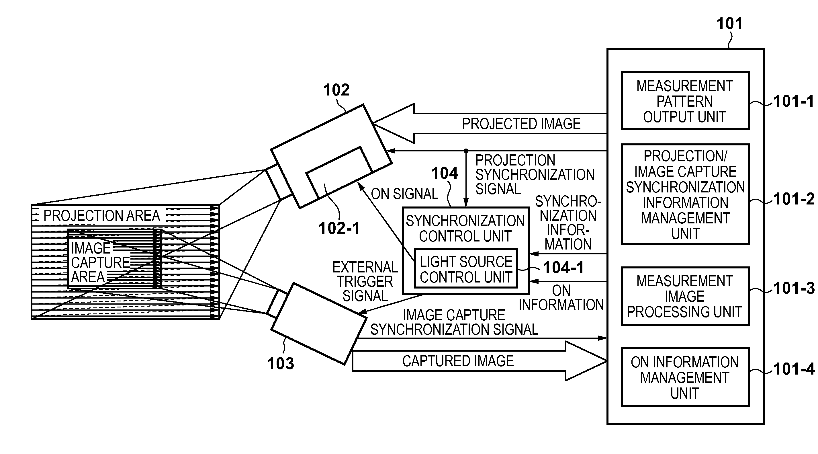
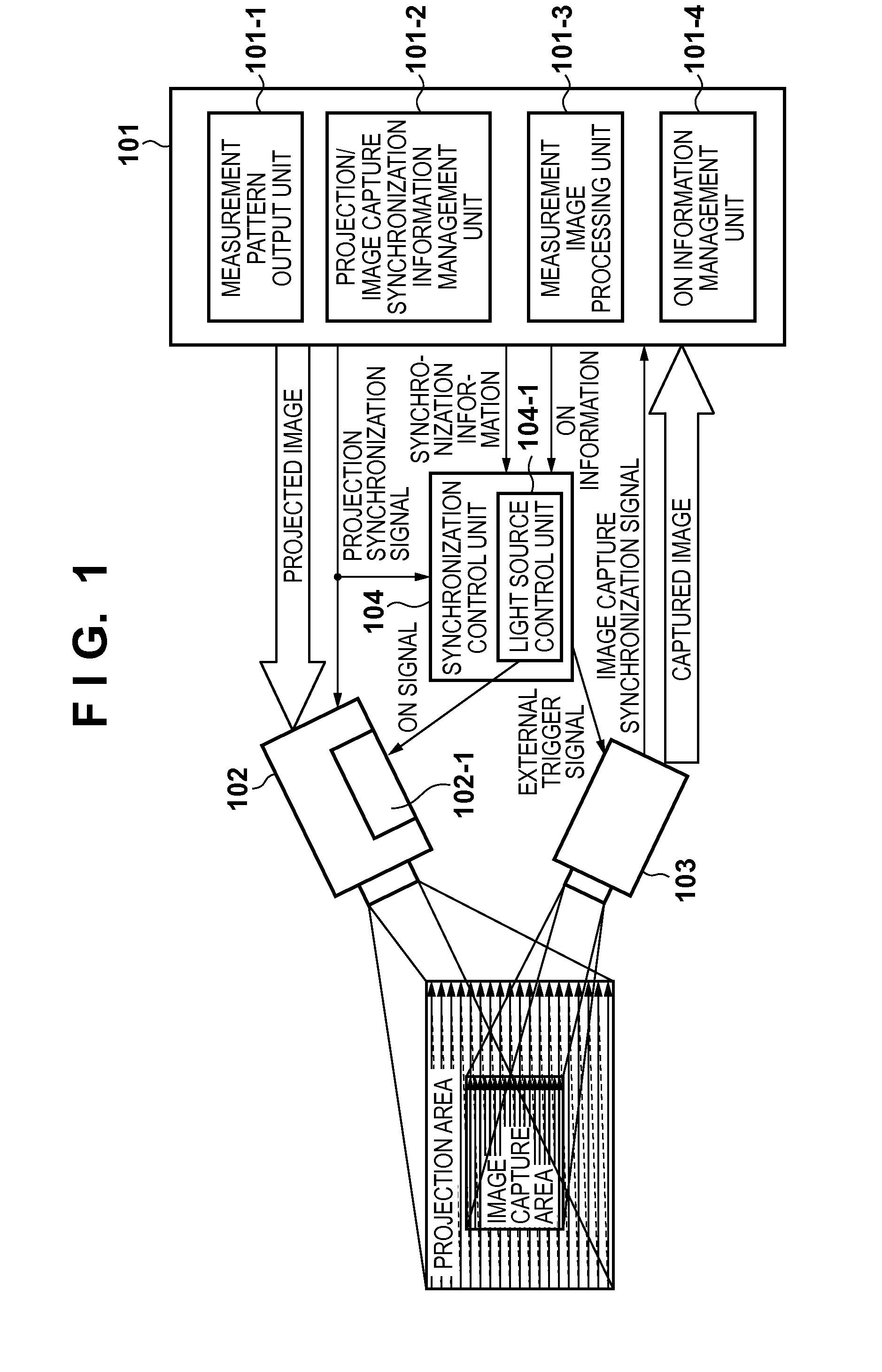
[0028]The configuration of a three dimensional measurement apparatus which functions as an information processing apparatus in the first embodiment will be described with reference to FIG. 1. The three dimensional measurement apparatus includes an overall control unit 101, projection unit 102, image capture unit 103, and synchronization control unit 104.

[0029]The overall control unit 101 includes a measurement pattern output unit 101-1, projection / image capture synchronization information management unit 101-2, measurement image processing unit 101-3, and ON information management unit 101-4. The projection unit 102 includes a light source unit 102-1. The synchronization control unit 104 includes a light source control unit 104-1.

[0030]The overall control unit 101 controls each processing unit including the measurement pattern output unit 101-1, projection / image capture synchronization information management unit 101-2, measurement image processing unit 101-3, and ON information man...

case 1

(case 1)

(Hp—st+Hp−Hs) / ((n+bk)×f−ΔHp / p)≧N≧Hp—st / ((n+bk)×f−ΔHp / p) for N≧0  (2)

case 2

(case 2)

(Hp—st+Hp−Hs—st−Hs) / ((n+bk)×f−ΔHp / p)≧N≧(Hp—st−Hs—st) / ((n+bk)×f−ΔHp / p) for N≧0  (3)

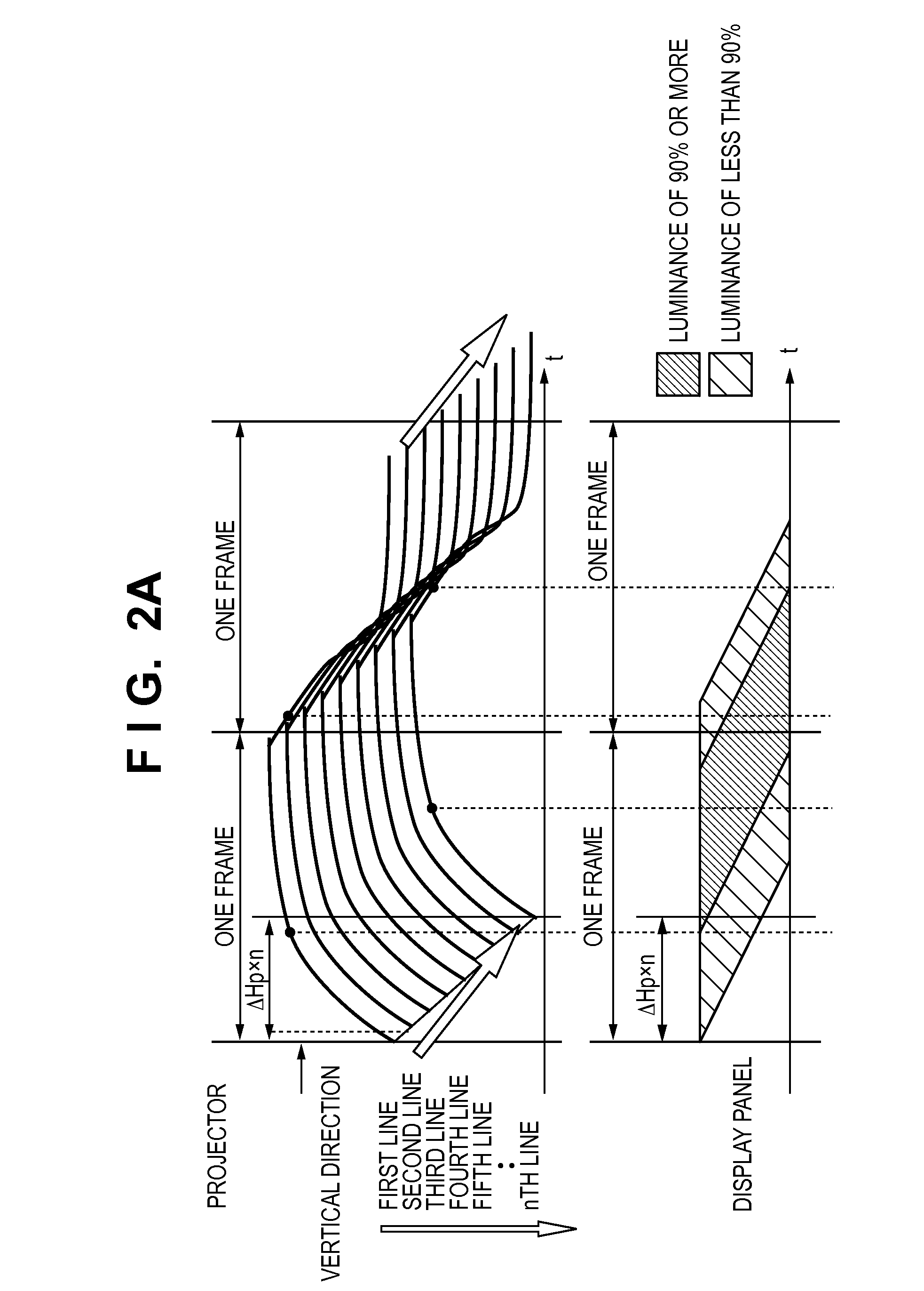
[0106]This means that in case 1, the time obtained by subtracting the exposure time Hs of the image capture unit 103 from the effective projection time Hp of the projection unit 102, and adding the projection start offset value Hp_st from the difference is the moratorium period in which the difference in time generated between projection scanning and image capture scanning within one frame period can be absorbed, and the value obtained by dividing this moratorium period by the difference in time for each line generated between projection scanning and image capture scanning becomes the maximum number of vertical lines of image capture, which satisfies relation (2). Hence, an image capture area defined up to this number of vertical lines can be captured. In addition, the projection start offset time Hp_st is the period in which the image capture unit 103 stands by for image capture using the diff...


PUM


Abstract

An information processing apparatus comprises projection means for projecting a projection pattern generated by a display device onto a target object by turning on a variable ON / OFF light source; image capture means for capturing an image of the target object onto which the projection pattern is projected; calculation means for calculating an image capture period of said image capture means based on a response property of the display device and image capture characteristics of said image capture means; and control means for controlling to synchronize the image capture period of said image capture means and a projection period of said projection means by keeping the light source ON during the image capture period.

Description

TECHNICAL FIELD[0001]The present invention relates to an information processing apparatus, a control method therefor, and a computer-readable storage medium.BACKGROUND ART[0002]In the field of industrial machine vision, three dimensional measurement techniques are known as technology components. A method of performing three dimensional measurement using machine vision will briefly be described hereinafter. First, a target object to be measured is irradiated with light which bears the information of a two dimensional pattern, and an image of the target object to be measured onto which the two dimensional pattern is projected is captured by a camera. Then, based on the periodicity of the two dimensional pattern, the captured image is analyzed to obtain distance information to the target object to be measured. This distance information indicates the distance from the camera to the target object to be measured or the depth of, for example, the three dimensional surface structure. Becaus...

Claims


Application Information

Patent Timeline
Patent Type & Authority Applications(United States)
IPC IPC(8): G01B11/25
CPCG01B11/254G01B11/25H04N9/3179H04N9/3194
Inventor CHIDA, MAKOTO
Owner CANON KK
Learn More