
Nebulizer for Charged Aerosol Detection (CAD) System

a technology of charged aerosol and nebulizer, which is applied in the direction of lighting and heating apparatus, combustion types, instruments, etc., can solve the problems of compromising the ability of the cad system to quantify analytes contained within droplets with high degree of sensitivity and reproducibility, and achieves the effect of facilitating the identification of higher electrical currents and steady electrical currents

Active Publication Date: 2014-12-04
DIONEX CORP
View PDF1 Cites 15 Cited by
  • Summary
  • Abstract
  • Description
  • Claims
  • Application Information

AI Technical Summary

Benefits of technology

The invention provides a nebulizer for a CAD system that can generate droplets and separate them based on their size. This allows the detector to sense smaller particle sizes and establish a steady current. This steady baseline current helps identify higher current peaks as samples are injected and separated in the chromatographic column. The technical effect of this is that it improves the accuracy and sensitivity of the CAD system.

Problems solved by technology

It is generally desirable to generate a spray of droplets of uniformly small diameters, since droplets having relatively large diameters may not have adequate time to dry (i.e., to fully evaporate the solvent) and form particles of non-volatile residue prior to reaching the discharge source, which may in turn compromise the ability of the CAD system to quantify analytes contained within the droplets with high degrees of sensitivity and reproducibility.

Method used


Image

  • Nebulizer for Charged Aerosol Detection (CAD) System
  • Nebulizer for Charged Aerosol Detection (CAD) System
  • Nebulizer for Charged Aerosol Detection (CAD) System

Examples


Embodiment Construction

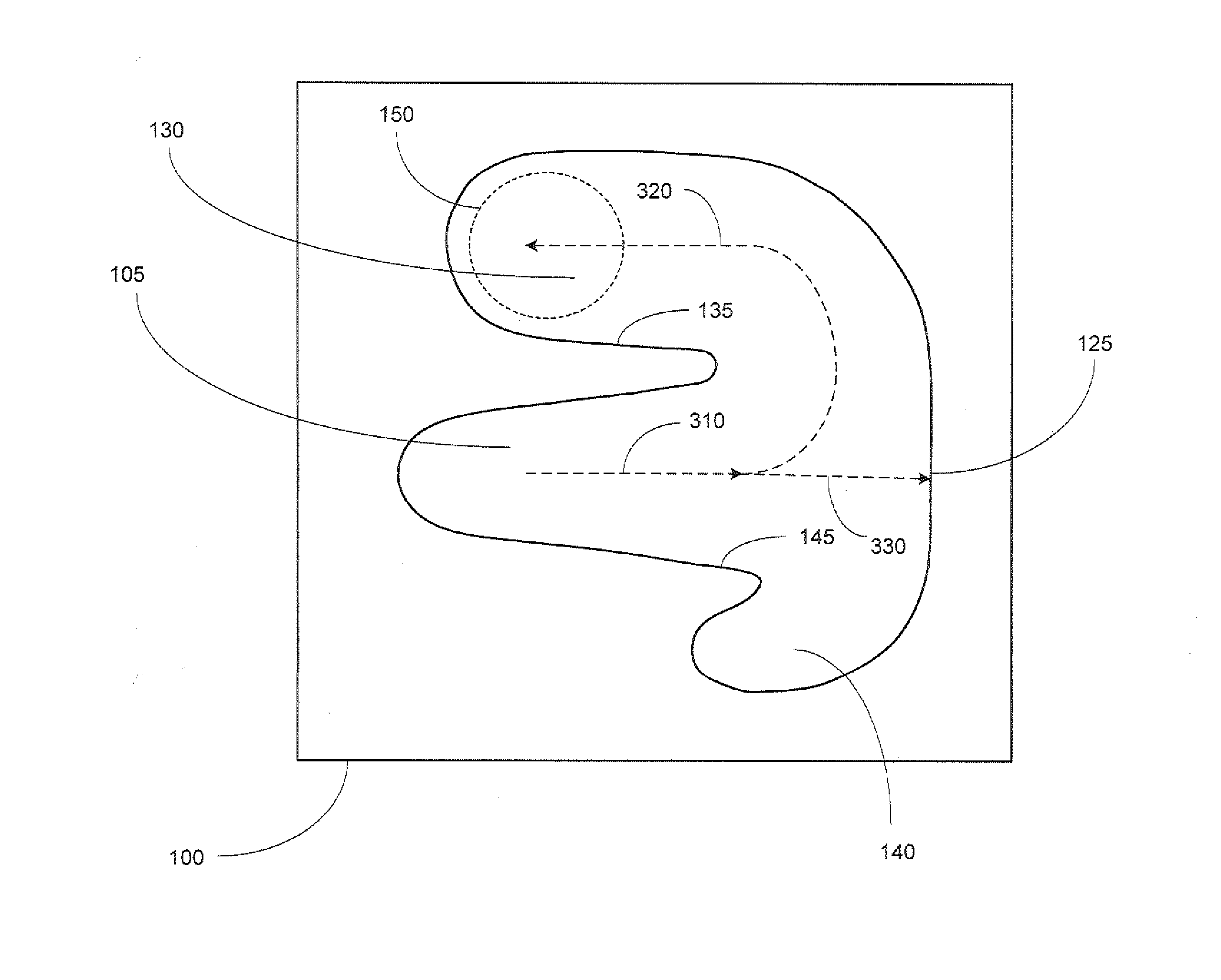
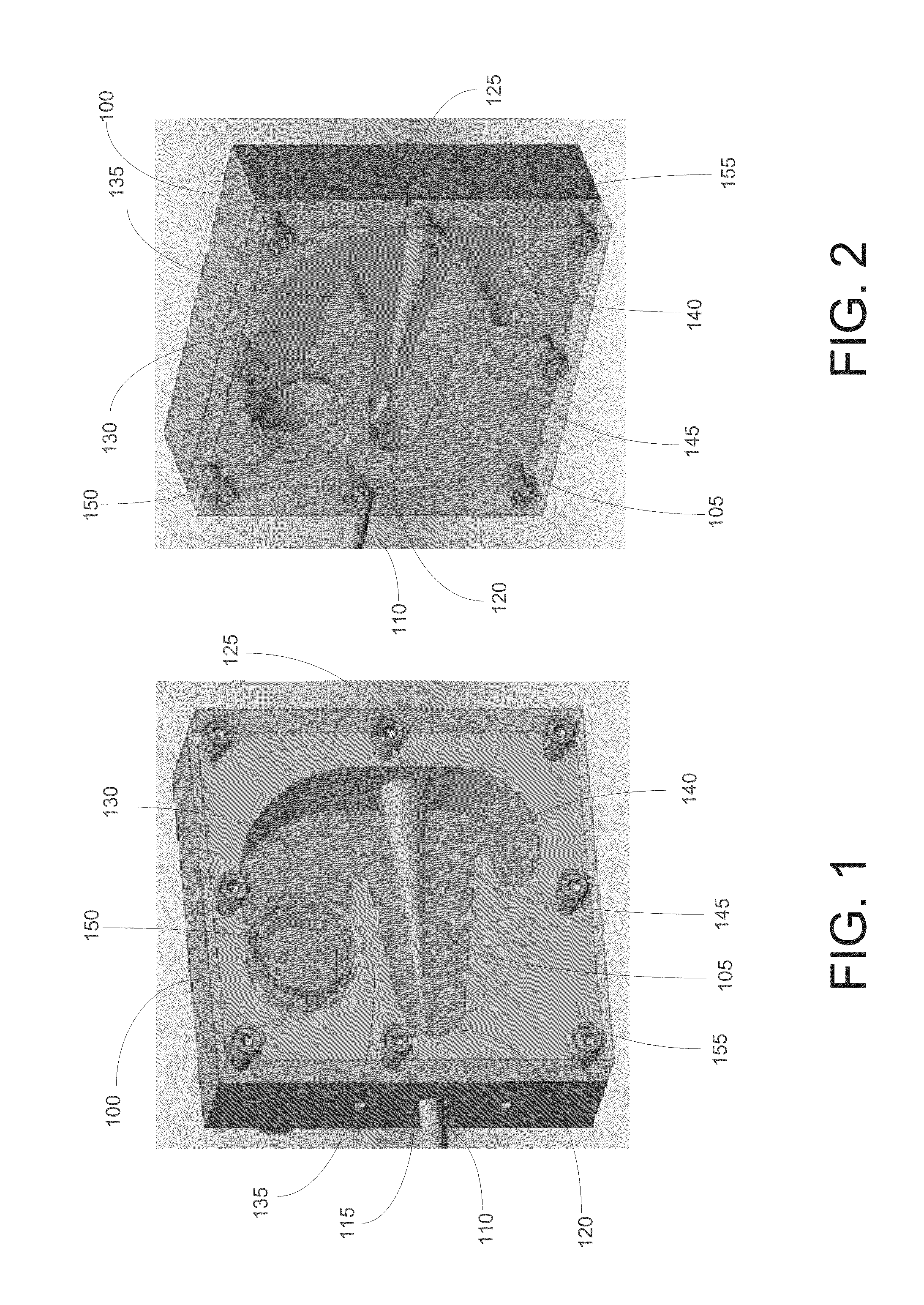
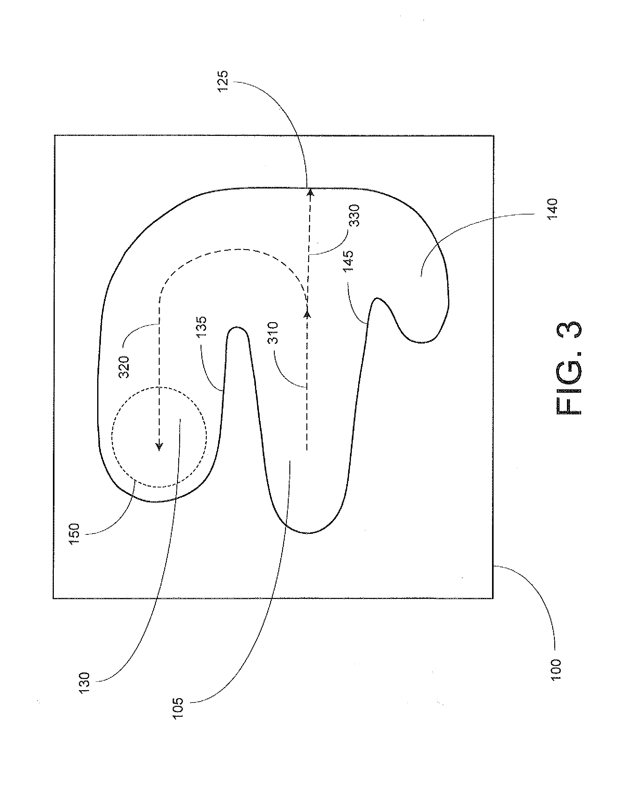
[0013]FIGS. 1-3 depict a nebulizer constructed in accordance with an embodiment of the present invention. The nebulizer includes a spray chamber body 100 having a central region 105 into which the sample spray is introduced by means of a pneumatic spray emitter 110, which is positioned within a port 115 penetrating the front wall 120. The tip of emitter 110 is horizontally spaced from (note: the terms “horizontal”, “vertical” and their variants are used herein for ease of explanation, and should not be construed as limiting the spray chamber to any particular orientation) and positioned in opposition to a medial portion (alternatively referred to herein as the “rear surface”) of back wall 125. Spray chamber further includes an upper region 130 partially divided from central region 105 by means of a horizontally projecting rib or partition 135, and a lower region 140 partially divided from central region 105 by means of a horizontally projecting rib or partition 145.

[0014]Referring n...


PUM

PropertyMeasurementUnit
diameteraaaaaaaaaa
distanceaaaaaaaaaa
distanceaaaaaaaaaa

Abstract

A nebulizer for a charged aerosol detection (CAD) system is disclosed. The nebulizer is provided with a spray emitter for generating a spray of droplets within a central region of a spray chamber. The central region is separated from an upper region by a horizontally projecting rib, which defines a passageway between the central and upper regions. The major direction of droplet travel within the upper region is substantially reversed with respect to the major direction of droplet travel within the central region. Larger droplets are unable to negotiate the turn from the central to upper regions and impinge on a rear surface of the spray chamber. Removal of larger droplets has the advantageous effect of enabling the detector to sense a smaller range of particle sizes, which establishes a relatively steady electrical current at the detector.

Description

CROSS-REFERENCE TO RELATED APPLICATIONS[0001]This application claims the priority benefit of U.S. Provisional Patent Application No. 61 / 828,629 for “Nebulizer for Charged Aerosol Detection (CAD) System”, filed May 29, 2013, the disclosure of which is hereby incorporated by reference.FIELD OF THE INVENTION[0002]The present invention relates generally to devices for detecting and quantifying components of a liquid sample stream, and more particularly to a nebulizer for use with a charged aerosol detection system.BACKGROUND OF THE INVENTION[0003]Charged aerosol detection is a popular and valuable technique for the detection and quantification of substances present in a liquid sample stream, and is particularly well-suited to use in connection with liquid chromatography applications. Briefly described, a charged aerosol detection (CAD) system consists of a nebulizer for generating a spray of droplets from a liquid sample stream (for example, the effluent from a chromatographic column), ...

Claims


Application Information

Patent Timeline
Patent Type & Authority Applications(United States)
IPC IPC(8): G01N30/84B05B7/00
CPCG01N30/84G01N2030/8464B05B7/0012B05B7/0876G01N30/64G01N2030/8452G01N2030/847G01N2015/0019
Inventor YIM, ALAN DANIELGAMACHE, PAUL H.MCCARTHY, RYAN S.
Owner DIONEX CORP
Learn More