
Mechanical filter-based pollution control system to remediate cooking emissions

a pollution control system and filter technology, applied in separation processes, transportation and packaging, filtration separation, etc., can solve problems such as emission remediation, and achieve the effect of removing greas

Active Publication Date: 2014-11-27
AJEMIAN ROBERT C
View PDF1 Cites 21 Cited by
  • Summary
  • Abstract
  • Description
  • Claims
  • Application Information

AI Technical Summary

Benefits of technology

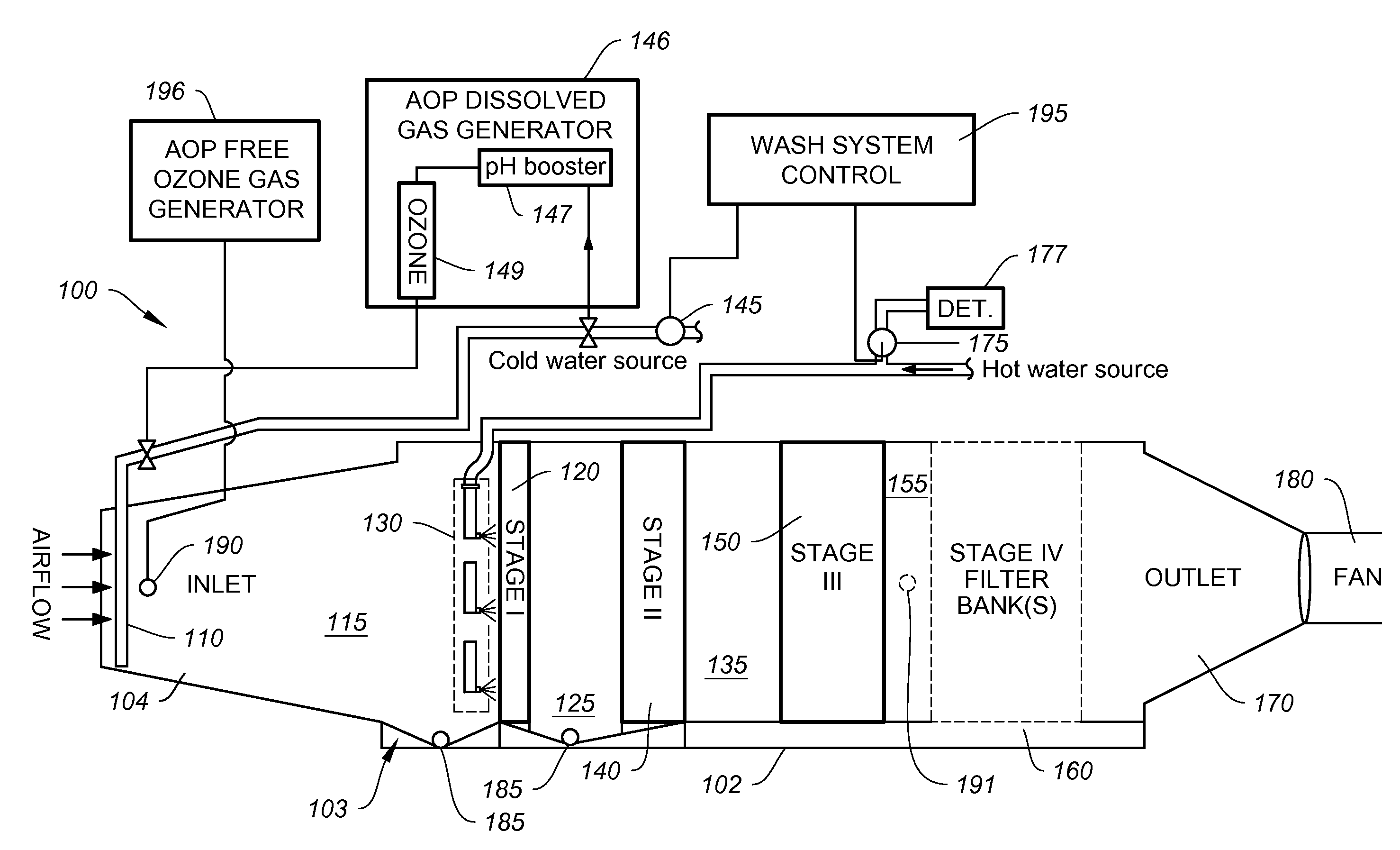
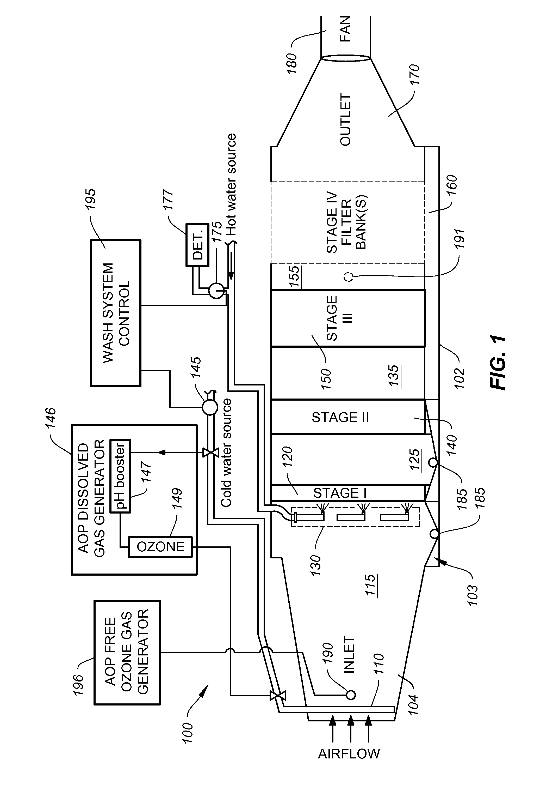
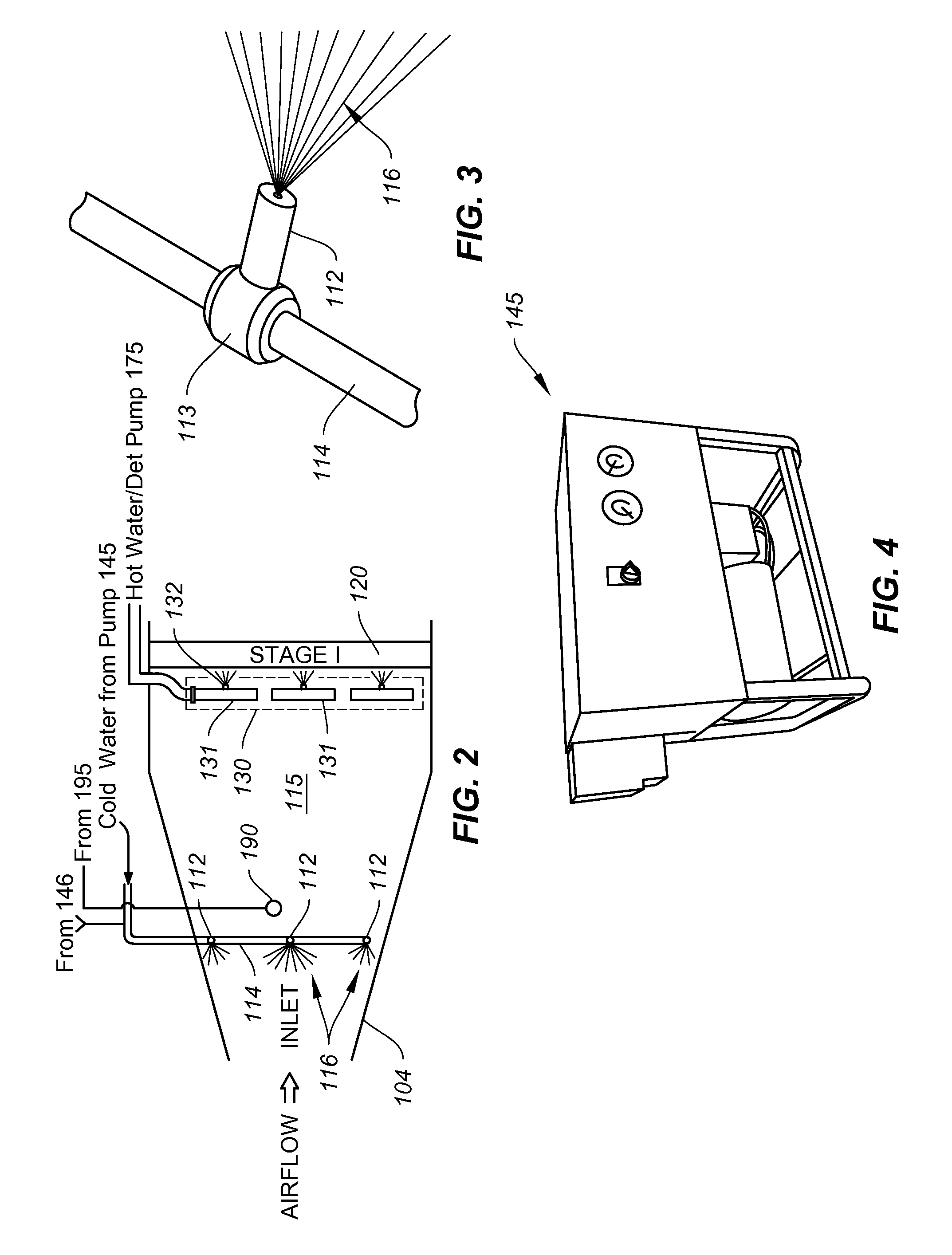
The present invention is a mechanical filter-based air pollution control system for removing particle and gas phase pollutants in a waste airstream from commercial cooking operations. The system includes a housing with an inlet and an outlet, an exhaust fan attached to the outlet for drawing the waste airstream into the inlet and through the housing to the outlet, and a fogger assembly attached to the inlet for spraying fog droplets into the waste airstream. The system also includes a first stage metal filter for filtering particle pollutants, a second stage filter for removing particle and gas phase pollutants, a third stage filter for removing sub-micron particle and gas phase pollutants, and a fourth stage filter for removing condensed particle pollutants. The system further includes injection means to inject activated ozone for initiating advanced oxidation processes (AOPs) upon contact with the waste airstream. The system can effectively remove various particle and gas phase pollutants from the waste airstream to achieve air pollution control.

Problems solved by technology

The most severe challenge to cooking emission remediation has been demonstrated repeatedly to be the emissions generated by gas char broiling of ground beef patties, with the severity of emissions being proportionately related to the fat content and the degree of well doneness of the beef patties.

Method used


Image

  • Mechanical filter-based pollution control system to remediate cooking emissions
  • Mechanical filter-based pollution control system to remediate cooking emissions
  • Mechanical filter-based pollution control system to remediate cooking emissions

Examples


Embodiment Construction

[0037]In general, and as to be shown in further detail below, example embodiments are directed to a mechanical filter-based air pollution control system having a washable first stage filter that removes particle pollutants such as grease and smoke, and gaseous odorous pollutants generated within a waste airstream from commercial cooking operations by a commercial kitchen cooking ventilation hood. The pollution control system incorporates novel and advanced chemical and physical technologies either separately or in combination to achieve maximal removal efficiencies of these air pollutants.

[0038]As to be shown in more detail hereafter, the system includes a fogger assembly that is combined with a plurality of progressively more efficient filters arranged within the system housing, including a stage 1 reactor filter, a stage 2 combination wool / synthetic media layered filter, and a stage 3 oil-mist media filter that assimilates the characteristics and DOP ratings of a HEPA media filter...


PUM

PropertyMeasurementUnit
sizeaaaaaaaaaa
diameteraaaaaaaaaa
distanceaaaaaaaaaa

Abstract

A mechanical filter-based air pollution control system for removing particle and gas phase pollutants in a waste airstream exhausted from commercial cooking operations is described, which includes a housing enclosing at least three filter stages to remove particle and gas pollutants in the airstream. The example system may include a fogger assembly that sprays fog droplets into the waste airstream to condense a portion of gas phase pollutants into condensed particles, a wash mechanism including spray nozzles to wash surfaces of the first stage filter to remove grease therefrom, and injection means for injecting activated ozone, which comprises ozone with a surplus of hydroxyl radicals, into the housing to initiate advanced oxidation processes (AOPs) to decompose particle and gas phase pollutants within the waste airstream in the filters. Where activated ozone is employed, the system includes a fourth stage filter that adsorbs and retains gas phase pollutants for subsequent oxidation.

Description

CROSS-REFERENCE TO RELATED APPLICATION[0001]The present application claims the benefit under 35 U.S.C. §119(e) of U.S. Provisional Patent Application No. 61 / 827,191 to the inventor, filed May 24, 2013, the entire contents of which is hereby incorporated by reference herein.BACKGROUND[0002]1. Field[0003]Example embodiments in general relate to a mechanical filter-based pollution control system to remediate cooking emissions.[0004]2. Related Art[0005]The emission profile from commercial cooking operations has been well studied and shown to consist of particles (aerosols), semi-volatile organic compounds (sVOCs), volatile organic compounds (VOCs) and inorganic volatile species. The particles give rise to visual smoke and the VOCs give rise to odors.[0006]The mass, size distribution and organic chemistry profile of the emissions can vary widely and are functions primarily of the type of cooking apparatus and the chemical and structural composition of the raw food being cooked. The most ...

Claims


Application Information

Patent Timeline
Patent Type & Authority Applications(United States)
IPC IPC(8): B01D46/00B01D53/00B01D53/44B01D53/76
CPCB01D46/0023B01D53/76B01D53/44B01D46/0082B01D46/0036B01D53/002B01D53/75B01D53/78B01D2251/104B01D2258/0275B01D46/62B01D46/79B01D50/10
Inventor AJEMIAN, ROBERT C.
Owner AJEMIAN ROBERT C
Learn More