
Control device and control method

a control device and induction motor technology, applied in the direction of electric generator control, dynamo-electric converter control, dynamo-electric gear control, etc., can solve the problems of deterioration of drivability, strange or uncomfortable driving, etc., to curb the increase of the temperature of the particular switching device, improve the drivability, and ensure the power performance

Active Publication Date: 2014-11-27
TOYOTA JIDOSHA KK
View PDF12 Cites 3 Cited by
  • Summary
  • Abstract
  • Description
  • Claims
  • Application Information

AI Technical Summary

Benefits of technology

The invention provides a control device and control method for an induction motor when an inverter is in a locked state. The control method ensures the motor operates at the necessary power to release the inverter from the locked state while preventing the temperature of the inverter's switching devices from increasing and affecting the driver's comfort or the motor's performance.

Problems solved by technology

However, sliding-down of the vehicle on which the induction motor is installed has already occurred in the locked state, and, if the vehicle is further moved backward under the above control, from this condition, the driver may feel strange or uncomfortable, and the drivability may deteriorate.

Method used


Image

  • Control device and control method
  • Control device and control method
  • Control device and control method

Examples


Embodiment Construction

[0022]A vehicular induction motor control device according to one embodiment of the invention will be described with reference to the drawings. An electric vehicle driven by an induction motor is taken as one example, and the vehicular induction motor control device installed on the electric vehicle will be described. This invention is not limitedly applied to the induction motor control device installed on the electric vehicle, but may also be applied to a vehicular induction motor control device installed on a hybrid vehicle, namely, a vehicle that runs with power of an engine and an induction motor.

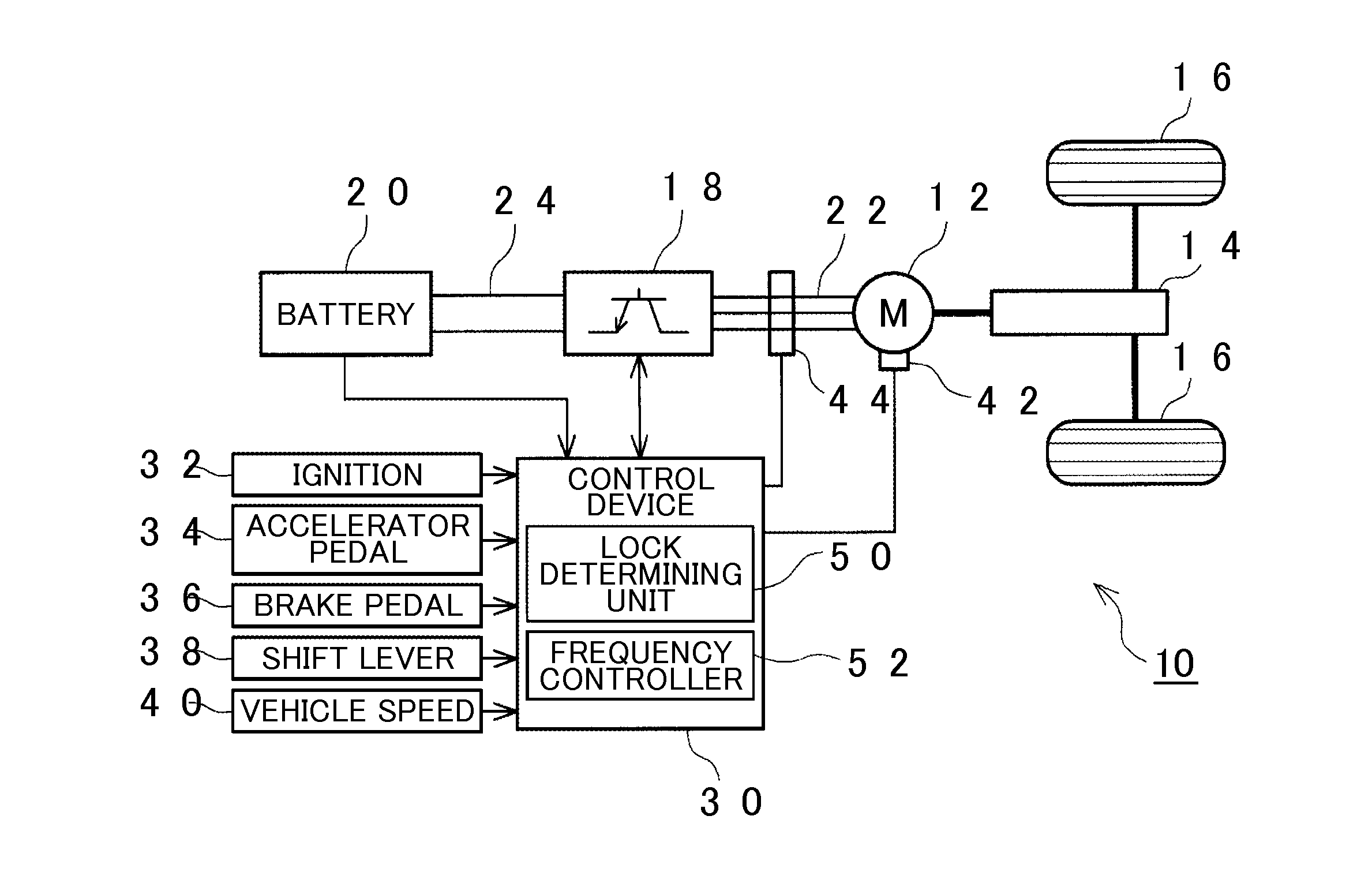
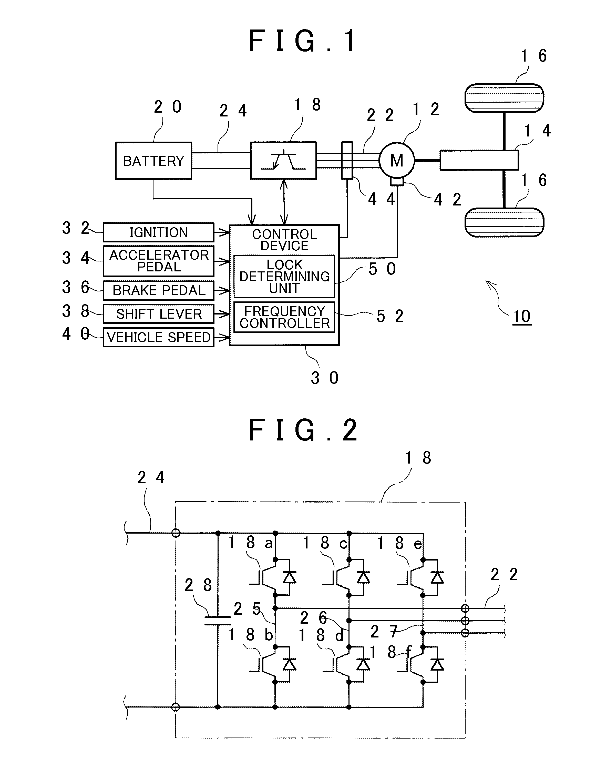
[0023]Initially, the construction of an electric vehicle 10 on which the vehicular induction motor control device according to this embodiment is installed will be described with reference to FIG. 1. FIG. 1 schematically shows the construction of the electric vehicle 10 according to this embodiment.

[0024]The electric vehicle 10 has an induction motor 12 as a prime mover. Drive wheels 1...


PUM


Abstract

A control device for an induction motor that drives a vehicle includes an electronic control unit. The electronic control unit i) controls torque of the induction motor when an inverter that controls supply of electric current to the induction motor is in a locked state, so as to release the inverter from the locked state, ii) determines whether the inverter is in the locked state, iii) controls a slip frequency of the induction motor when it determines that the inverter is in the locked state, and iv) superimposes a frequency that actual torque does not substantially respond, on the slip frequency, so that an electric frequency lies in a region outside a lock region in which the inverter is in the locked state.

Description

INCORPORATION BY REFERENCE[0001]The disclosure of Japanese Patent Application No. 2013-107433 filed on May 21, 2013 including the specification, drawings and abstract is incorporated herein by reference in its entirety.BACKGROUND OF THE INVENTION[0002]1. Field of the Invention[0003]The invention relates to a control device and control method for a vehicular induction motor, and in particular to a control device and control method for a vehicular induction motor, which controls the induction motor that drives the vehicle so as to prevent overheating of an inverter that controls supply of electric current to the induction motor when the inverter is locked.[0004]2. Description of Related Art[0005]Electric vehicles or hybrid vehicles that run with power of electric motors are known. In this type of vehicle, when the motor rotates during normal running of the vehicle, alternating current flows through each of switching devices of an inverter that controls supply of current to the motor. ...

Claims


Application Information

Patent Timeline
IPC IPC(8): H02P23/00B60L3/00H02P21/22H02P23/07H02P25/026H02P27/06H02P27/08
CPCH02P23/0095B60L3/0061H02P23/08H02P23/28H02P27/06H02P2207/01Y02T10/64
Inventor OTA, TAKASHI
Owner TOYOTA JIDOSHA KK
Learn More