
Apparatus for electrical-assisted incremental forming and process thereof

a technology of incremental forming and apparatus, applied in the direction of heat treatment apparatus, shaping tools, furnaces, etc., can solve the problems of increasing the manufacturing cost of a given component, and requiring stronger tools and dies

Active Publication Date: 2014-11-27
PENN STATE RES FOUND +1
View PDF2 Cites 10 Cited by
  • Summary
  • Abstract
  • Description
  • Claims
  • Application Information

AI Technical Summary

Benefits of technology

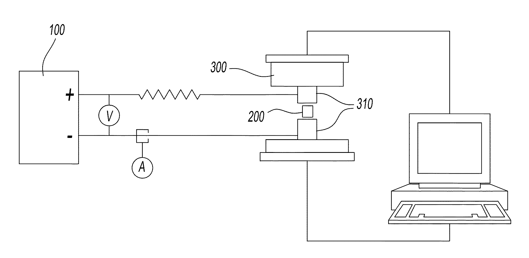
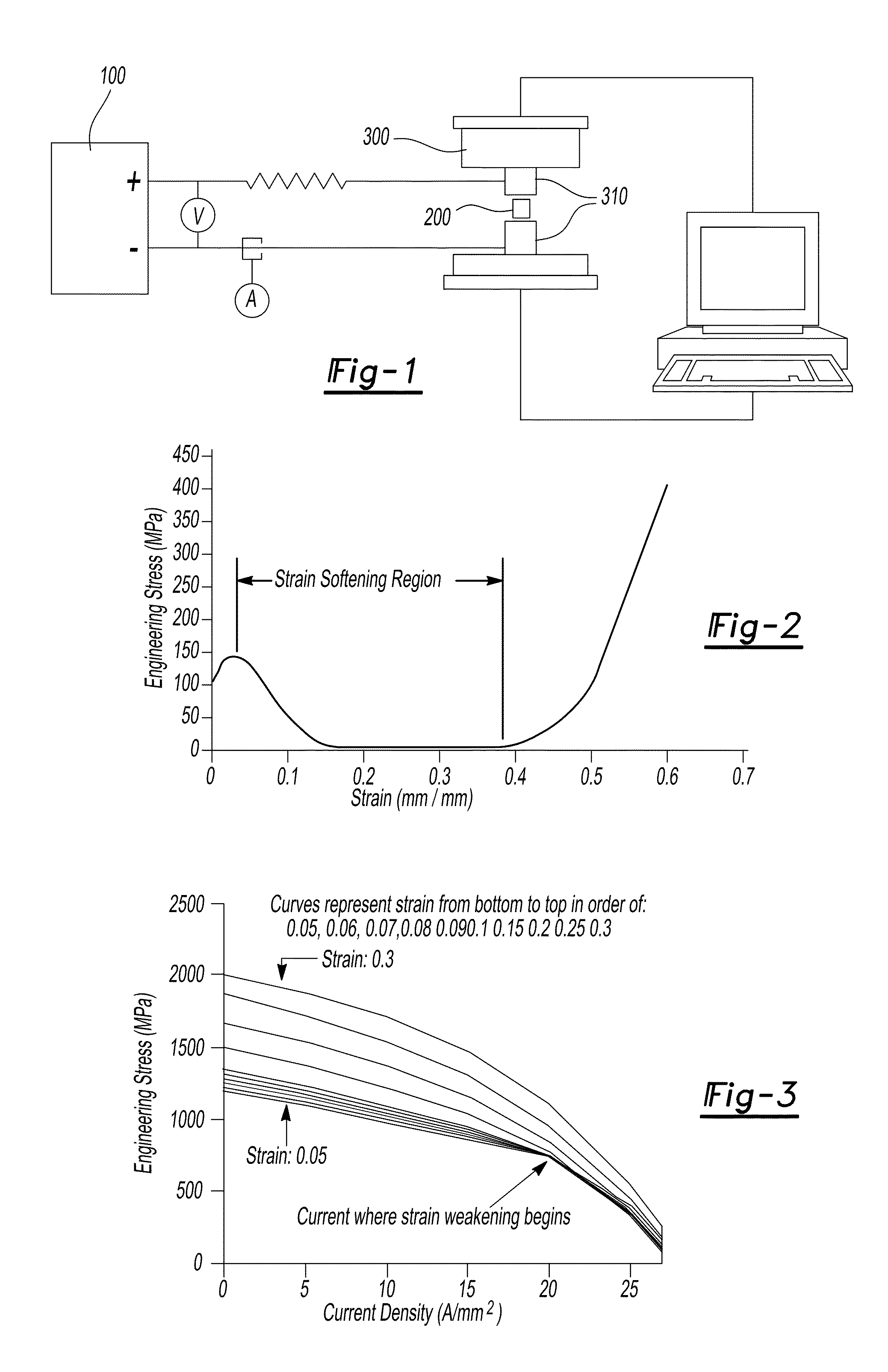
The patent describes an apparatus and process for forming a piece of sheet metal by passing an electrical direct current through the sheet metal. The apparatus includes a computer numerical controlled machine with an arcuate tipped tool that moves the sheet metal and an electrode that is synchronized with the tool. The machine can make incremental deformations to the sheet metal by moving the tool and the electrode in the same direction and at the same distance. The process includes attaching the sheet metal to the machine, making the deformations with the tool, and passing the electrical current through the electrode to achieve the desired current density. The technical effect is the ability to form sheet metal with electrical direct current while maintaining desired properties, such as density and strength, at specific locations.

Problems solved by technology

For example, as the required force for deformation increases, larger equipment must be utilized, stronger tools and dies are required, tool and die wear increase, and / or more energy is consumed in the process.
Furthermore, all of these factors increase the manufacturing cost of a given component and a process or apparatus that would decrease the required force for deformation and / or increase the amount of deformation that can be achieved without fracture and / or retain the deformed shape after unloading could have a significant impact on many manufacturing processes.
However, significant drawbacks to deforming materials at elevated temperatures exist, such as increased tool and die adhesion, decreased die strength, decreased lubricant effectiveness, decreased dimensional accuracy and consumption of materials for heating (which raises energy cost), and the need for additional equipment to be purchased.
Furthermore, dislocations are line defects which can be formed during solidification, plastic deformation, or be present due to the presence of impurity atoms or grain boundaries, and as such, dislocation motion is the motion of line defects through the material's lattice structure causing plastic deformation.

Method used


Image

  • Apparatus for electrical-assisted incremental forming and process thereof
  • Apparatus for electrical-assisted incremental forming and process thereof
  • Apparatus for electrical-assisted incremental forming and process thereof

Examples


Embodiment Construction

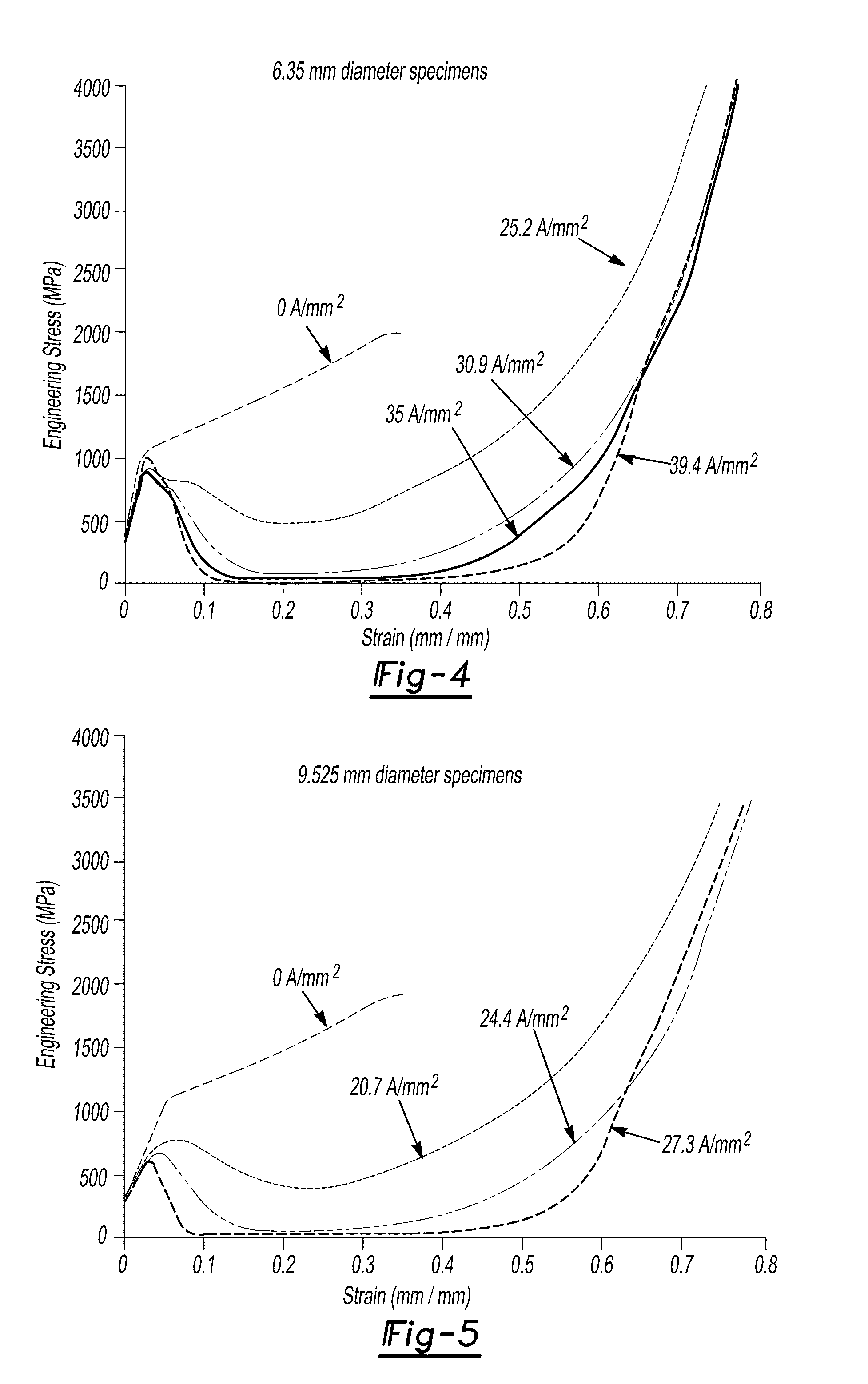
[0052]It is postulated that, as electrons scatter off different resistant sources, for example the same resistance areas for dislocation motion, the local stress and energy field increases. This occurs since, as electrons strike the areas with a given velocity, there is an increase in the amount of kinetic energy around the resistance area due to transference from the electron as its scatters. The local Joule heating effect due to the application of electrical current can soften the resistance. Therefore, dislocations can move through the areas of resistance with increased local energy fields with less resistance. Since these areas are at a higher potential, less energy is required for a dislocation to move therethrough. In addition, the energy required to break atomic bonds as dislocations move through the lattice structure decreases.

[0053]Overall, it is postulated that the effects of current passing through a metallic material should result in a net reduction in the energy require...


PUM

PropertyMeasurementUnit
diameteraaaaaaaaaa
diameteraaaaaaaaaa
weightaaaaaaaaaa

Abstract

A process and apparatus for forming a sheet metal component using an electric current passing through the component. The process can include providing an incremental forming machine, the machine having at least one arcuate tipped tool and at least electrode spaced a predetermined distance from the arcuate tipped tool. The machine is operable to perform a plurality of incremental deformations on the sheet metal component using the arcuate tipped tool. The machine is also operable to apply an electric direct current through the electrode into the sheet metal component at the predetermined distance from the arcuate tipped tool while the machine is forming the sheet metal component.

Description

CROSS-REFERENCE TO RELATED APPLICATIONS[0001]This application is a continuation-in-part of U.S. patent application Ser. No. 13 / 221,304 filed Aug. 30, 2011, which is a continuation-in-part of U.S. patent application Ser. No. 12 / 194,355 filed Aug. 19, 2008, which is a continuation-in-part of U.S. patent application Ser. No. 12 / 117,970 filed May 9, 2008, which claims priority of U.S. Provisional Patent Application Ser. No. 60 / 916,957 filed May 9, 2007, both of which are incorporated herein by reference. This application also claims priority of U.S. Provisional Patent Application Ser. No. 61 / 378,271 filed Aug. 30, 2010, from which U.S. patent application Ser. No. 13 / 221,304 filed Aug. 30, 2011 claims priority to, which is also incorporated herein by reference.STATEMENT REGARDING FEDERALLY SPONSORED RESEARCH OR DEVELOPMENT[0002]This invention was made with government support under Grant No. DE-EE0003460, awarded by the Department of Energy. The Government has certain rights in the invent...

Claims


Application Information

Patent Timeline
Patent Type & Authority Applications(United States)
IPC IPC(8): B21D26/00
CPCB21D26/00C21D7/02B21D31/005B21D37/16B21J1/06C21D1/09C21D1/40C21D7/13C21D9/0018C21D9/0068C21D9/46C21D9/48C21D2261/00
Inventor ROTH, JOHNCAO, JIAN
Owner PENN STATE RES FOUND
Learn More