
Muscle stimulation device

Active Publication Date: 2014-11-20
THE NAT UNIV OF IRELAND GALWAY +1
View PDF1 Cites 27 Cited by
  • Summary
  • Abstract
  • Description
  • Claims
  • Application Information

AI Technical Summary

Benefits of technology

The patent text describes a device that uses current sensing to monitor changes in skin impedance and reactance in real time. The device includes a current sensor with a feedback conductor and a current-limiting resistor to protect the feedback conductor from over-current and over-voltage. The device also has a stimulus envelope with a ramp-up time and ramp-down time that increase with increased stimulus intensity. The on-time of the stimulus is reduced while the ramp-up time and ramp-down time are elongated to maintain the ramp-up rate and total envelope duration.

Problems solved by technology

This pain is a limiting factor in the maximal stimulus that a user may tolerate and indirectly limits the maximal muscular contraction force that may be achieved.
This pain can also affect the tolerance of a user to NMES and their likelihood to adhere to a surface NMES type treatment regimen in both short and long term applications.
Furthermore, as NMES intensity increases and forceful muscular contractions are induced, further muscular pain similar to cramping or a spasm may be perceived by the user.
Again, this will limit the acceptability of NMES by the user and limit the potential benefit.

Method used


Image

  • Muscle stimulation device
  • Muscle stimulation device
  • Muscle stimulation device

Examples


Embodiment Construction

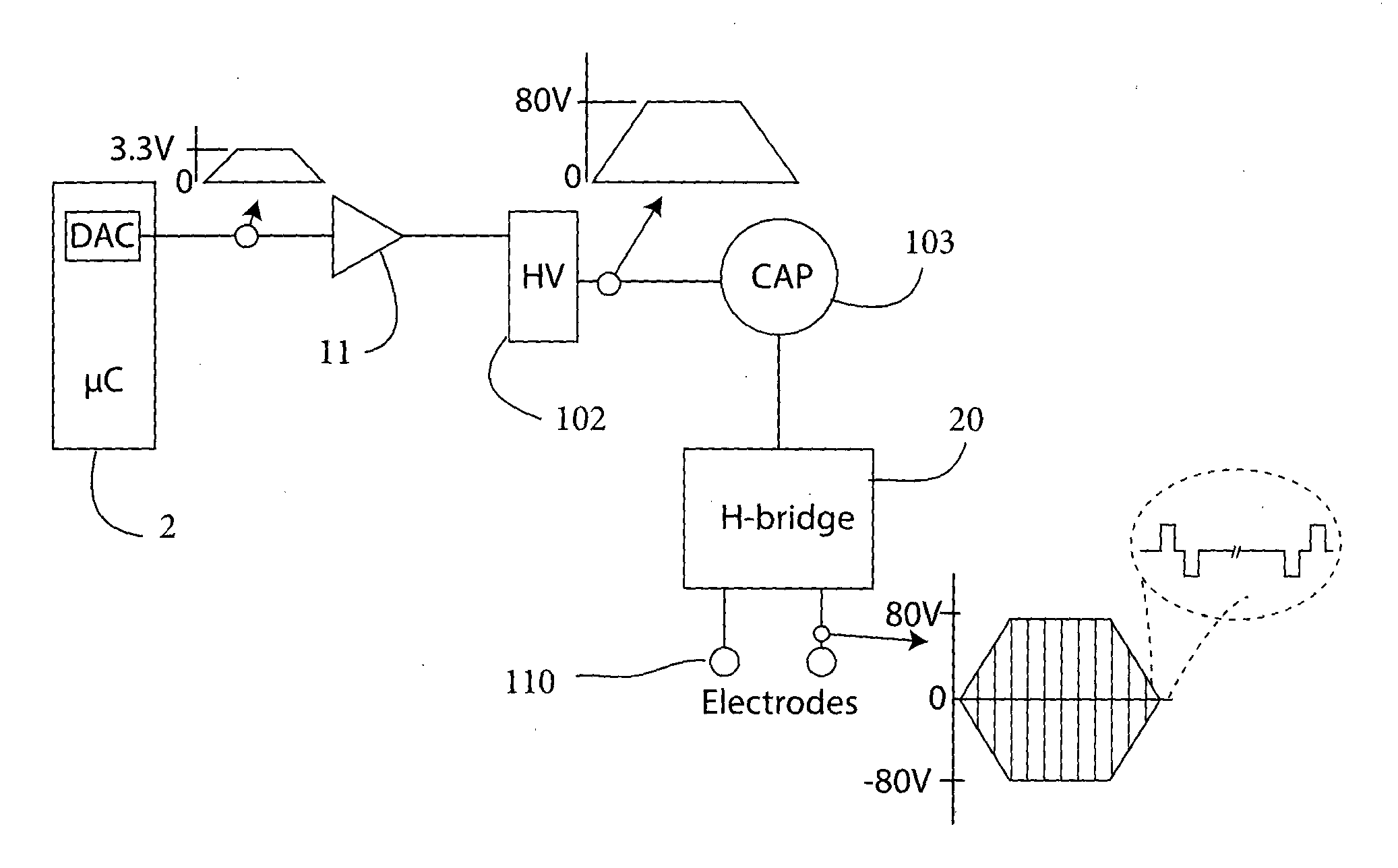
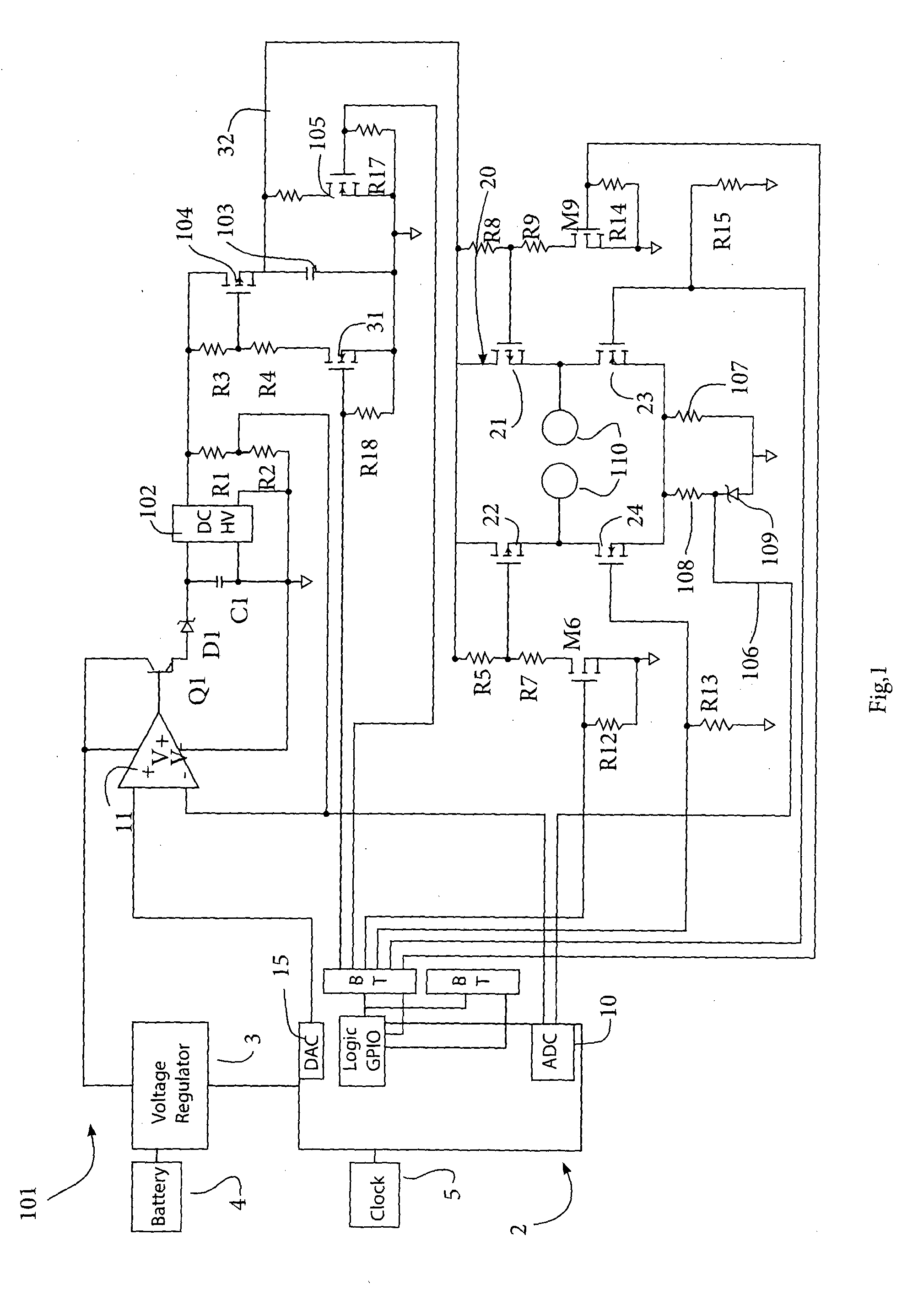
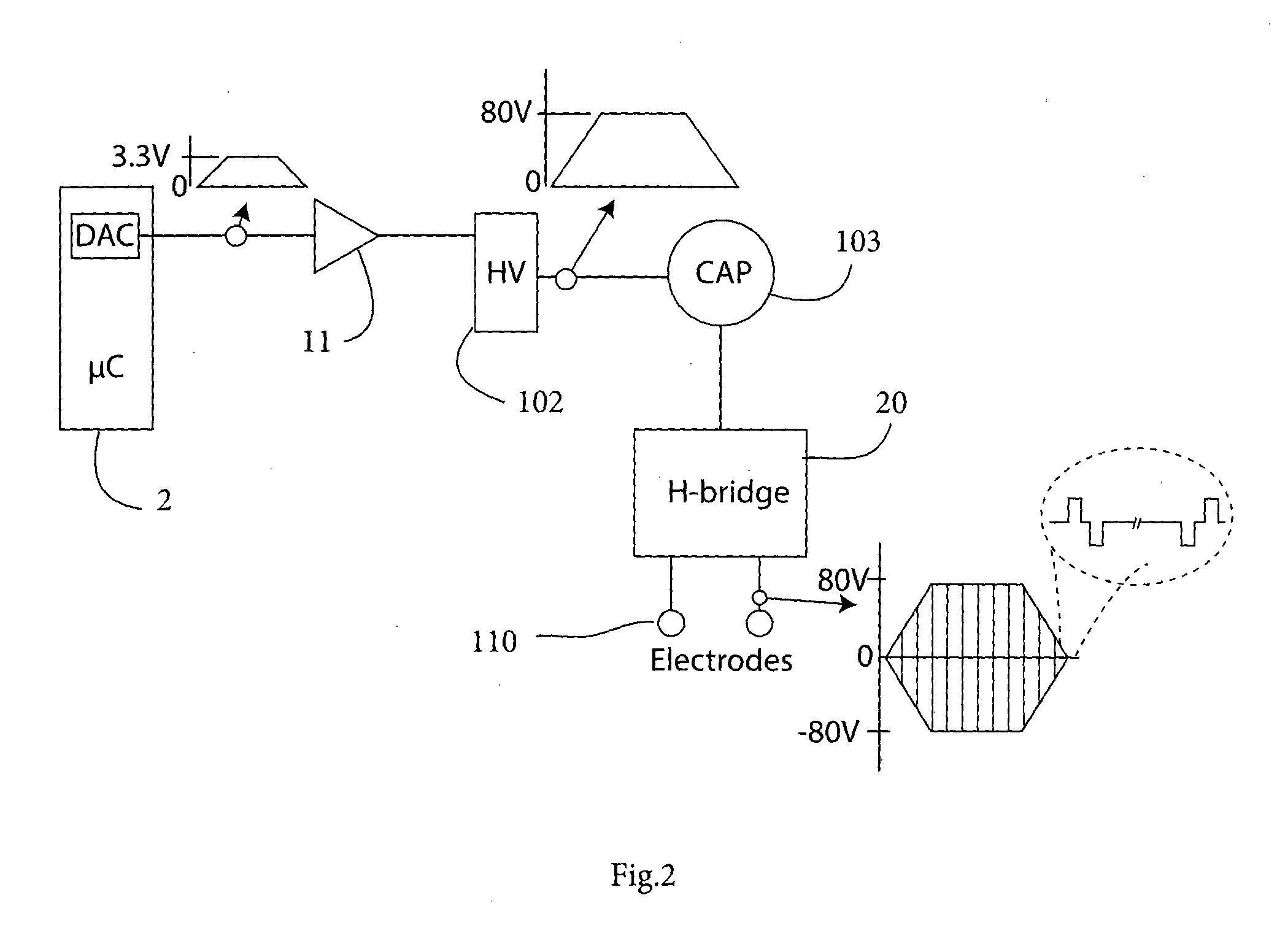
[0053]Referring to FIGS. 1 and 2 a stimulation device 101 comprises a micro-controller 2 connected to a voltage regulator 3, in turn connected to a battery DC power source. The micro-controller 2 is linked with a clock 5, and comprises an ADC 10 for sense inputs. It has a DAC 15 for providing analog control input to an op-amp 11. The op-amp 11 controls the flow of power to a high voltage supply 102. Thus, the output of the high voltage supply is an amplified DAC signal. The output of the high voltage supply 102 is connected across a pair of resistors R1 and R2, and a voltage-sensing tap from between these two resistors is linked back to the micro-controller 10 by a track 30, thereby providing a voltage feedback to the micro-controller in real time. Flow of current from the high voltage supply 102 is controlled by a FET switch 104.

[0054]The high voltage supply 102 has a 0 to 5V input voltage, n 0 to 100V output voltage, a 5 mA output current, and a typical frequency of 100 to 200 kHz...


PUM


Abstract

A surface NMES stimulation device the device has a control processor, a voltage regulator connected to a high voltage supply, a bridge of control switches, and electrodes or electrode terminals connected in the bridge to receive drive signals via the control switches. The processor directs a drive scheme for the bridge control switches in which charge build-up on a user's skin is allowed to dissipate to ground in an inter-pulse interval. An isolation capacitor isolates the high voltage supply from the electrodes, and charging of the capacitor only occurs if a switch allows it. Sensors senses supply voltage and bridge current and the processor monitors there to determine further stimulation and faults.

Description

FIELD OF THE INVENTION[0001]The invention relates to surface neuromuscular electrical stimulation (NMES).PRIOR ART DISCUSSION[0002]The application of an electrical stimulus through the skin to a motor neuron causing activation of its associated muscle is known as surface Neuromuscular Electrical Stimulation (NMES). There are numerous uses for NMES where the electrodes are fitted to the skin surface; the prevention of atrophy, improving blood circulation, drop-foot correction, or stroke rehabilitation for example. Tolerance of the user to the surface NMES stimulus is critical in these and other applications. In long term applications where NMES is required over extended periods of time without supervision, device safety is also important for successful treatment.[0003]When a NMES stimulus is applied via surface electrodes with the purpose of inducing muscular contraction, sensory neurons in the skin are also activated inadvertently. The resulting muscular contraction increases in pro...

Claims


Application Information

Patent Timeline
IPC IPC(8): A61N1/36
CPCA61N1/36014A61N1/14A61N1/36003A61N1/36031A61N1/36034A61N1/36125
Inventor O LAIGHIN, GEAROIDBREEN, PAULO'KEEFFE, DEREKCONWAY, RICHARDBIRLEA, SINZIANA LULIA
Owner THE NAT UNIV OF IRELAND GALWAY
Learn More