Device triggering and apn-based congestion control

a technology of apn and apn, applied in the direction of frequency-division multiplex, machine-to-machine/machine-type communication service, instruments, etc., can solve the problems of inability to store the sm-bo timer without a corresponding context, congestion or overload of the network, etc., and achieve the effect of reducing the number of sm-bo timers and reducing the number of sm-bo tim

Active Publication Date: 2014-11-20
PANASONIC INTELLECTUAL PROPERTY CORP OF AMERICA
View PDF19 Cites 64 Cited by
  • Summary
  • Abstract
  • Description
  • Claims
  • Application Information

AI Technical Summary

Benefits of technology

This patent aims to improve congestion control in a network by reducing the signaling exchange required for device triggering procedures in case of network congestion. The invention proposes a method for determining which external networks a terminal can connect to after being triggered from a message received from a subscriber server. The method includes transmitting information to the terminal about the congested networks to prevent data transmission. The signaling used for the communication can be non-access-stratum (NAS) signaling. Overall, this invention enhances network congestion control and allows efficient communication between terminals and servers.

Problems solved by technology

It was concluded that the numerous MTC devices acting in simultaneous manner could cause congestion or overload to the network.
For example, when the SGSN / MME rejects a new PDP context or PDN connection request, the SGSN / MME would not have PDP or PDN context for the UE and it would be difficult to store the SM-BO timer without having a corresponding context.
However, this mechanism doesn't describe very precisely the impact of the APN-based SM congestion control, but rather is applicable for a general MM congestion control.
If the SM-BO timer is running in the UE, the UE is not allowed to send an SM request, and thus, the UE cannot establish / activate the PDP context.
Consequently, the UE is not able to send the UL data.
This is not efficient as paging is performed and radio resource connection (RRC) and NAS signalling connection are established for the device trigger request transmission and then released after the rejection oof the UE's NAS SM request.
Accordingly, the congestion control could not be performed efficiently in this scenario.
The reason is that through the paging, additional MM signalling to from the SGSN / MME would be caused, which is not desirable.
This situation may lead to different problems.

Method used


Image

  • Device triggering and apn-based congestion control
  • Device triggering and apn-based congestion control
  • Device triggering and apn-based congestion control

Examples


Embodiment Construction

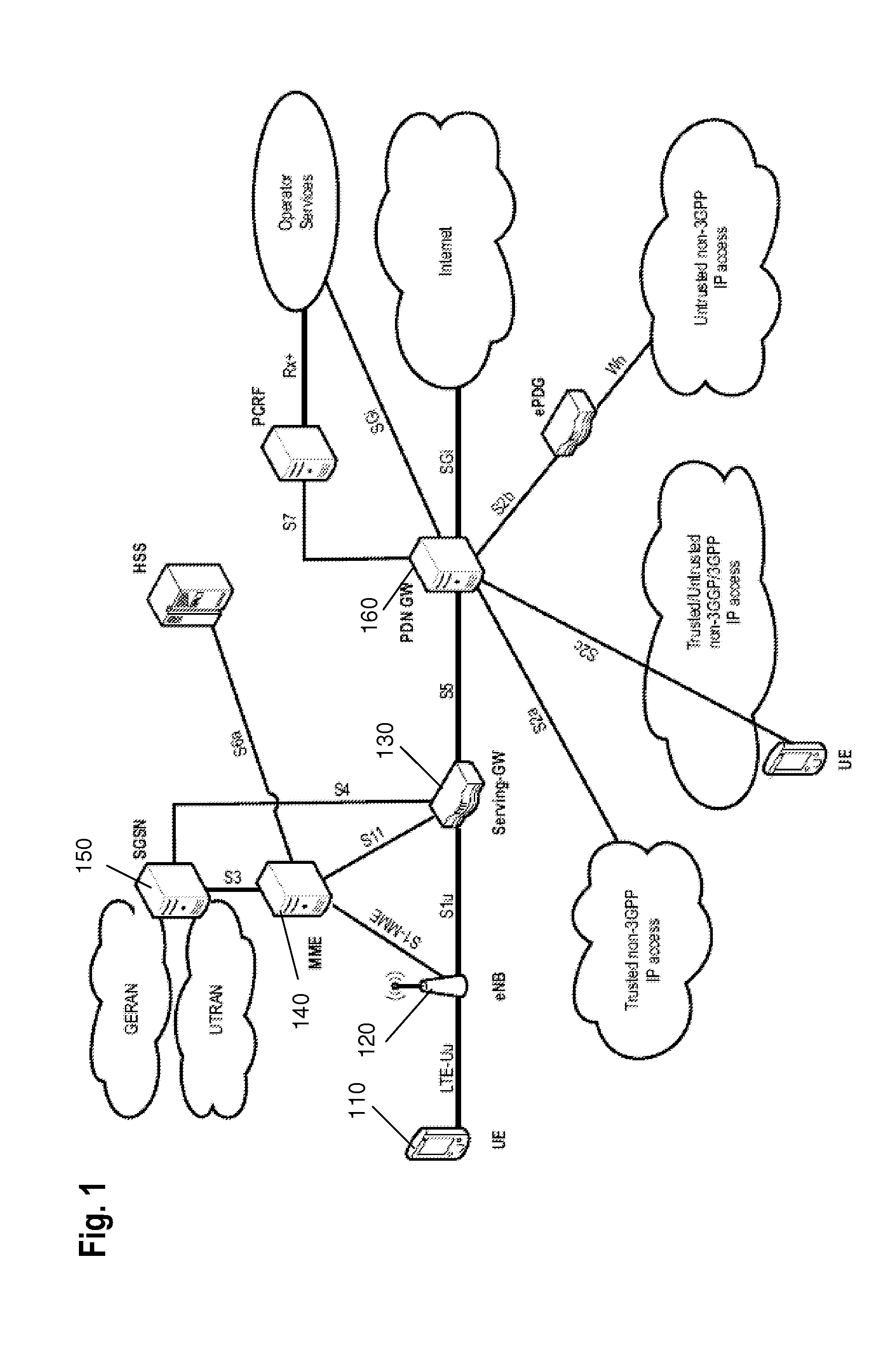
[0103]In this document, the term such as “mobile node” designates a physical entity within a communication network. One node may have several functional entities. A functional entity refers to a software or hardware module that implements and / or offers a predetermined set of functions to other functional entities of a node or the network. Nodes may have one or more interfaces that attach the node to a communication facility or medium over which nodes can communicate. Similarly, a network entity may have a logical interface attaching the functional entity to a communication facility or medium over it may communicate with other functional entities or correspondent nodes.

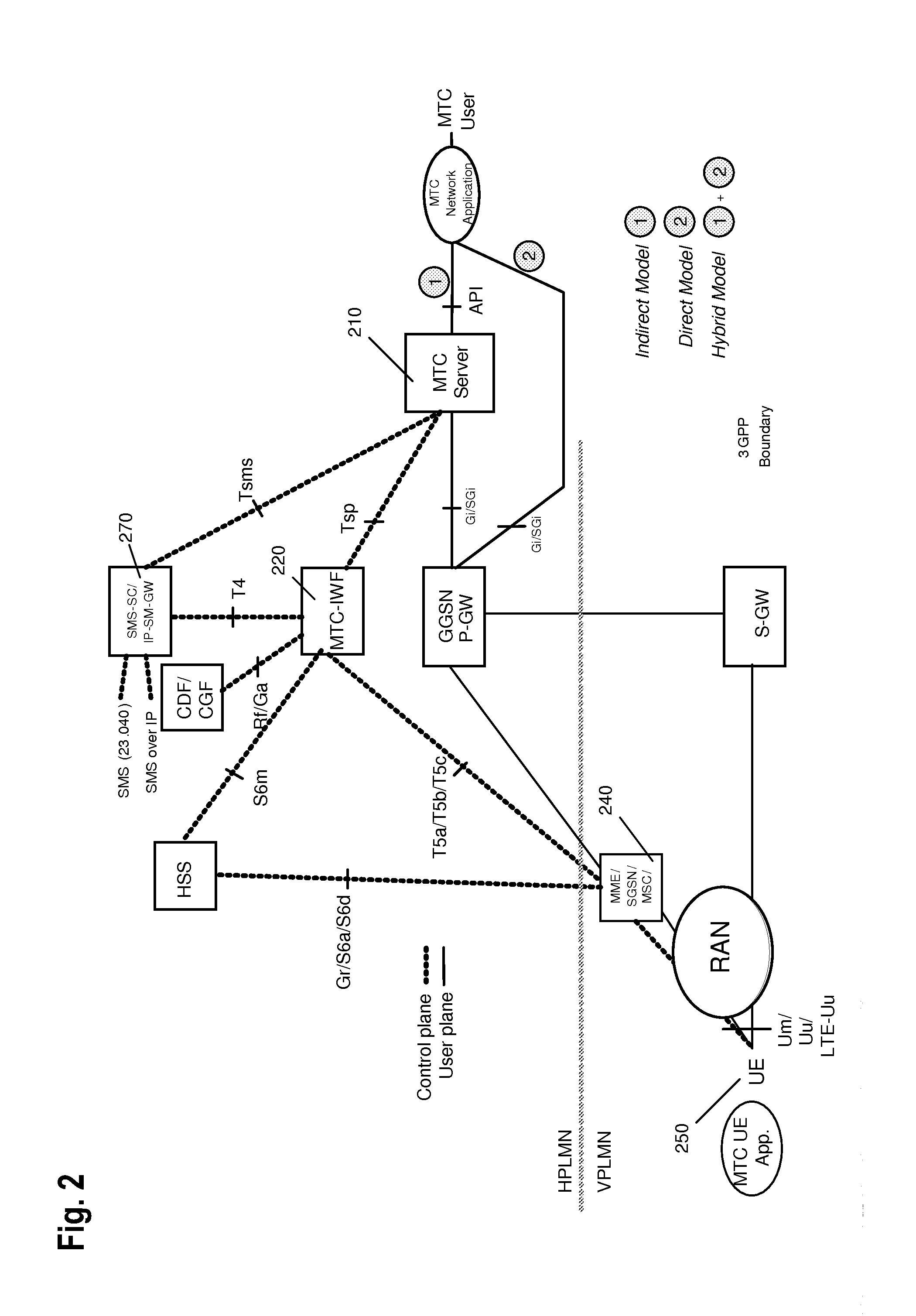
[0104]The term “server” or “triggering server” here refers to an entity which may be within the network or in an external network or an external node. It may be, for instance a server for automatically collecting data from a (MTC) terminal or a plurality of terminals and capable of sending to the terminal triggering re...


PUM


Abstract

The present invention relates to device triggering in case of a congestion control. A triggering server transmits a device trigger request to a terminal over a communication network including a serving network node. The network node evaluates whether the connection can be established from the terminal to the server, including determining whether the network is congested and / or whether a back-off timer is running and / or the remaining time of the back-off timer at the terminal. Then the network node transmits a delivery delay indication to a device triggering control server to provide it with the delivery delay indication indicating at least one of impossibility of establishing the connection to the server after the trigger or a data transmission delay.

Description

[0001]The invention relates to triggering a terminal by a server in a communication system. In particular, the invention relates to providing an efficient triggering mechanism taking into account congestion control.TECHNICAL BACKGROUND[0002]The 3rd generation Partnership Project (3GPP) organization specifies the architecture of mobile cellular networks such as like Global System for Mobile Communications (GSM) and Universal Mobile Telecommunications System (UMTS). Third-generation mobile systems (3G), based on WCDMA radio-access technology, such as UMTS, are being deployed on a broad scale all around the world. A first step in enhancing or evolving this technology was the introduction of the High-Speed Downlink Packet Access (HSDPA) and of the enhanced uplink, also referred to as High Speed Uplink Packet Access (HSUPA). In a longer time perspective it is however necessary to be prepared for further increasing user demands and be competitive against new radio access technologies. To ...

Claims


Application Information

Patent Timeline
IPC IPC(8): H04W28/12H04W76/02H04L47/267H04W4/70H04W76/10
CPCH04W76/02H04W28/12H04Q3/0045H04W28/0289H04W4/70H04W76/10
Inventor VELEV, GENADIBACHMANN, JENSASO, KEIGO
Owner PANASONIC INTELLECTUAL PROPERTY CORP OF AMERICA
Why Eureka
Try Eureka