Position Sensorless Step-Wise Freewheeling Control Method for Switched Reluctance Motor

a technology of switching reluctance motor and sensorless control method, which is applied in the direction of control system, electrical apparatus, ac motor control, etc., can solve the problems of reduced motor reliability, severe limitations in the applicability of switched reluctance motor, and increased motor cost and system complexity, so as to achieve high dynamic response and stability, high real-time feature, and high practicability

Active Publication Date: 2014-11-20
CHINA UNIV OF MINING & TECH
View PDF5 Cites 8 Cited by
  • Summary
  • Abstract
  • Description
  • Claims
  • Application Information

AI Technical Summary

Benefits of technology

The present invention is a method for controlling a switched reluctance motor system using dual switched-mode power converters for each phase. The method detects the phase current and switches on the upper tube and lower tube of the main switch of the phase in the power converter when the phase current reaches a preset threshold. This allows the motor to enter into negative voltage forced freewheeling state and then negative voltage natural freewheeling state without the need for a rotor-position sensor. The method has high real-time feature, dynamic response, stability, and practicability, making it widely applicable. It expands the application domain of switched reluctance motor systems and improves its operational reliability.

Problems solved by technology

Switched reluctance motors have simple and robust structure, and are suitable for use in harsh industrial environments; however, the existence of position sensors results in severely reduced motor reliability, increased motor cost and system complexity.
Moreover, since position sensors can not be mounted in some domains (e.g., compressor applications), the applicability of switched reluctance motors is severely limited.
Therefore, it is an inexorable trend to implement control without position sensor in the development of switched reluctance motors.
Since the given motor is required to be modeled in advance in this method, the universality of the method is limited; in addition, to measure the flux linkage (or inductance) in the modeling process or operation process, data acquisition and computation has to be carried out for a number of variables, resulting in error accumulation and degraded position detection accuracy; moreover, the detection error will be increased since the model is susceptible to the impact of motor aging.
The rotor position at the end position of minimum phase inductance can be obtained through phase current gradient method by detecting the peak phase current in the inductance rising zone; that method is not suitable for phase current chopping control; the ON-OFF angle adjustment range is limited, and the speed adjustment range is reduced during angular position control.

Method used


Image

  • Position Sensorless Step-Wise Freewheeling Control Method for Switched Reluctance Motor
  • Position Sensorless Step-Wise Freewheeling Control Method for Switched Reluctance Motor
  • Position Sensorless Step-Wise Freewheeling Control Method for Switched Reluctance Motor

Examples


embodiment 1

[0014]A Switched Reluctance Motor System that Employs Dual Switched-Mode Power Converters for each Phase

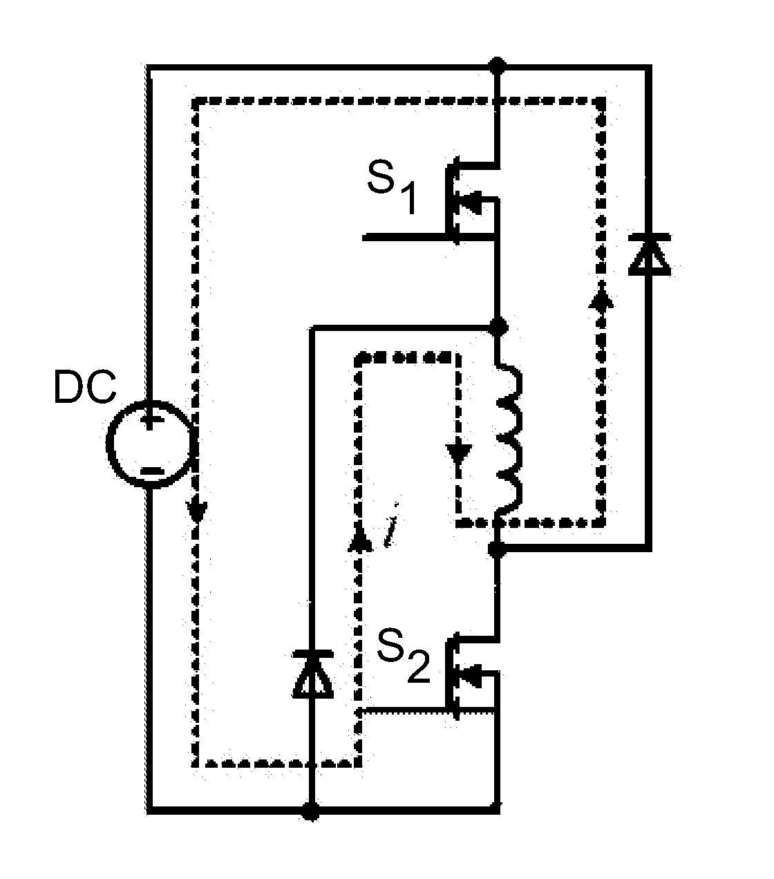
[0015]The system employs power supply, windings of a switched reluctance motor, and a power converter composed of main switch and diodes, wherein, the upper tube S1 and lower tube S2 for the main switch of a phase in the power converter are switched off, and the phase of the switched reluctance motor enters into DC negative voltage forced freewheeling state; a threshold is set for the winding current of the phase, and the phase current i is detected; the freewheeling path of the phase current i is shown in FIG. 1.

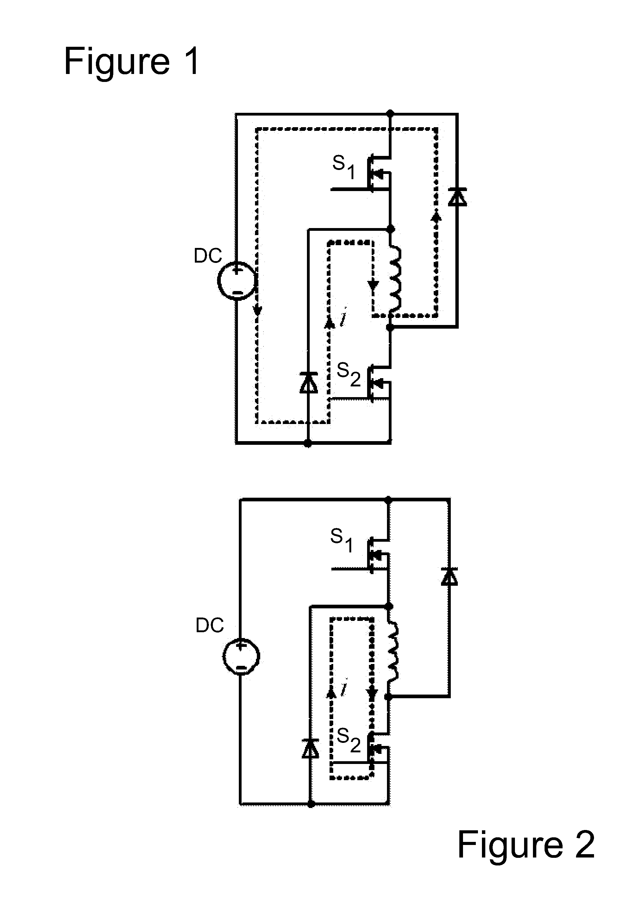
[0016]When the winding current i of the phase falls to the preset threshold, the lower tube S2 of the main switch of the phase in the power converter is switched on, and the phase in the switched reluctance motor enters into zero voltage natural freewheeling state, and the phase current i begins to rise up, the freewheeling path of phase current i is shown in FIG. 2.

[0017...

embodiment 2

[0018]A Switched Reluctance Motor System that Employs Dual Switched-Mode Power Converters for each Phase

[0019]The system employs power supply, windings of a switched reluctance motor, and a power converter composed of main switch and diodes, wherein, the upper tube S1 and lower tube S2 of the main switch of a phase in the power converter are switched off, and the phase of the switched reluctance motor enters into DC negative voltage forced freewheeling state; a threshold is set for the winding current of the phase, and the phase current i is detected; the freewheeling path of the phase current i is shown in FIG. 1.

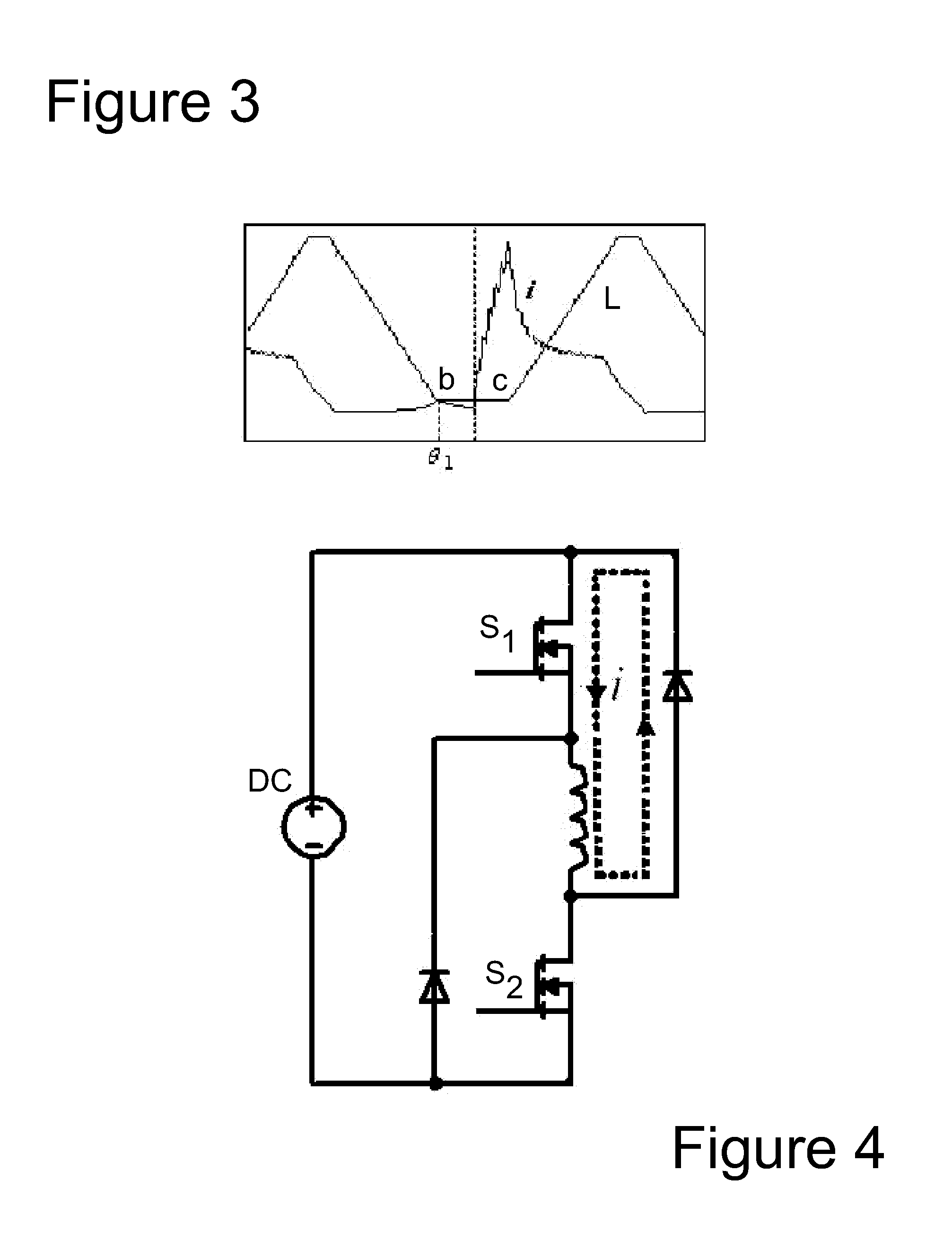
[0020]When the winding current i of the phase falls to the preset threshold, the upper tube S1 for the main switch of the phase in the power converter is switched on, and the phase of the switched reluctance motor enters into zero voltage natural freewheeling state, and the phase current i begins to rise up; the freewheeling path of phase current i is shown in FIG. 4.

[0021...


PUM


Abstract

A position sensorless step-wise freewheeling control method for a switched reluctance motor having dual switched-mode power converters for each phase doesn't require any additional external hardware, any rotor-position sensor, or storage of flux linkage data of the motor. After the upper and lower tubes of the main switch are switched off, and the phase of the switched reluctance motor enters into a negative voltage forced freewheeling state, the phase current is detected. When the phase current falls to a preset threshold, one of the upper or lower tubes is switched on and the phase enters into a zero voltage natural freewheeling state. When the phase current reaches a peak value, the rotor position becomes the start position of the minimum phase inductance and the rotor position is used as the switch-on position of the main switch. The upper and lower tubes are then switched on.

Description

FIELD OF THE INVENTION[0001]The present invention relates to a position sensorless control method for switched reluctance motor, which utilizes step-wise freewheeling and is applicable to switched reluctance motor systems that have different number of phase and employ dual switched-mode power converters for each phase.BACKGROUND OF THE INVENTION[0002]Switched reluctance motors have simple and robust structure, and are suitable for use in harsh industrial environments; however, the existence of position sensors results in severely reduced motor reliability, increased motor cost and system complexity. Moreover, since position sensors can not be mounted in some domains (e.g., compressor applications), the applicability of switched reluctance motors is severely limited. Therefore, it is an inexorable trend to implement control without position sensor in the development of switched reluctance motors. A variety of controlling methods without position sensor have been put forward at home a...

Claims


Application Information

Patent Timeline
Patent Type & Authority Applications(United States)
IPC IPC(8): H02P25/08
CPCH02P25/085H02P25/089H02P25/092H02P25/083
Inventor CHEN, HAOZENG, HUI
Owner CHINA UNIV OF MINING & TECH
Why Eureka
Try Eureka