
Second order harmonic cancellation for radio frequency front-end switches

a front-end switch and harmonic cancellation technology, applied in the field of radio frequency signal circuitry, can solve the problems of low insertion loss of rf switches, difficult linearity production, and large signal operation, and achieve the effect of improving harmonic suppression and low insertion loss

Active Publication Date: 2014-11-13
SKYWORKS SOLUTIONS INC
View PDF5 Cites 15 Cited by
  • Summary
  • Abstract
  • Description
  • Claims
  • Application Information

AI Technical Summary

Benefits of technology

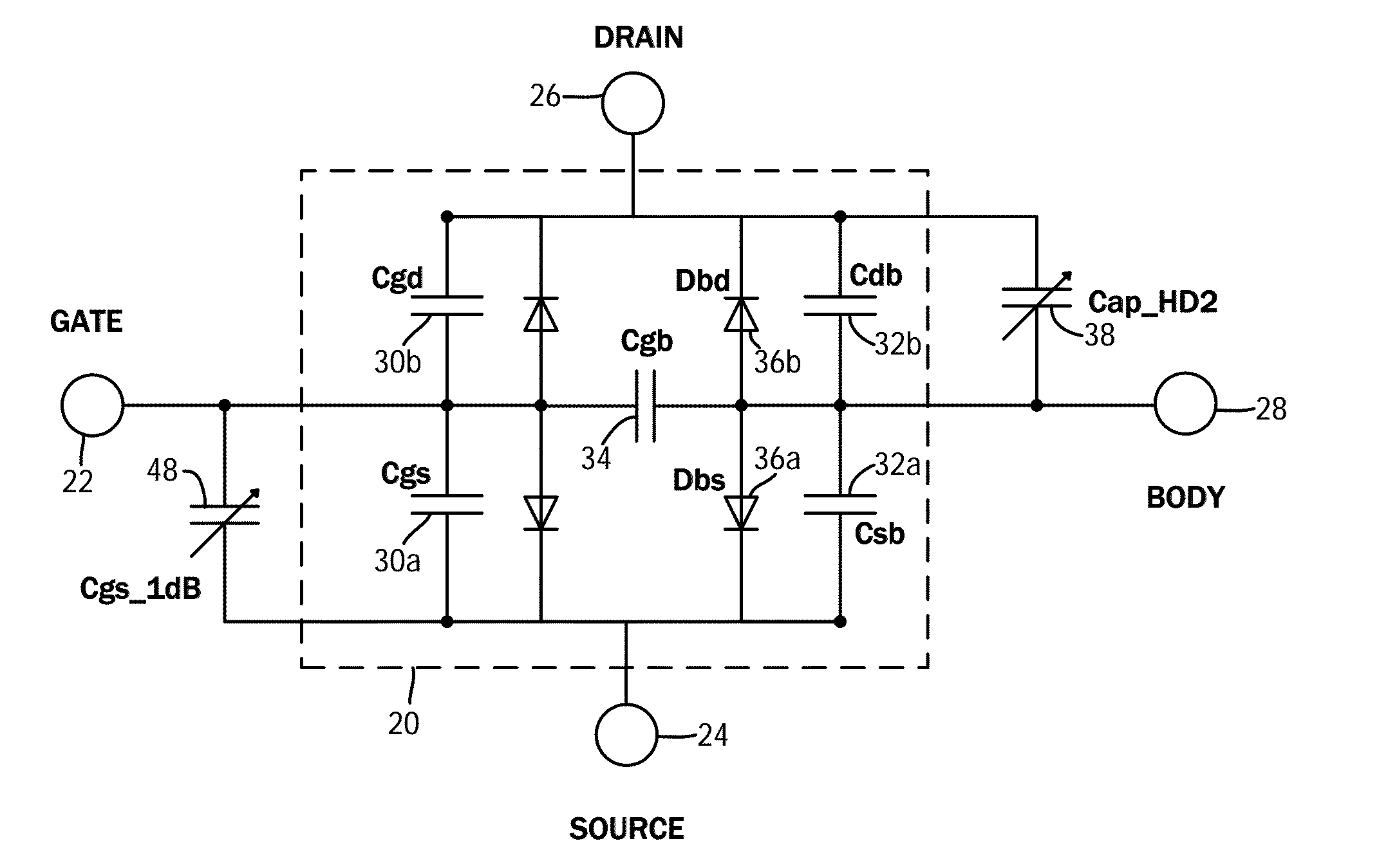
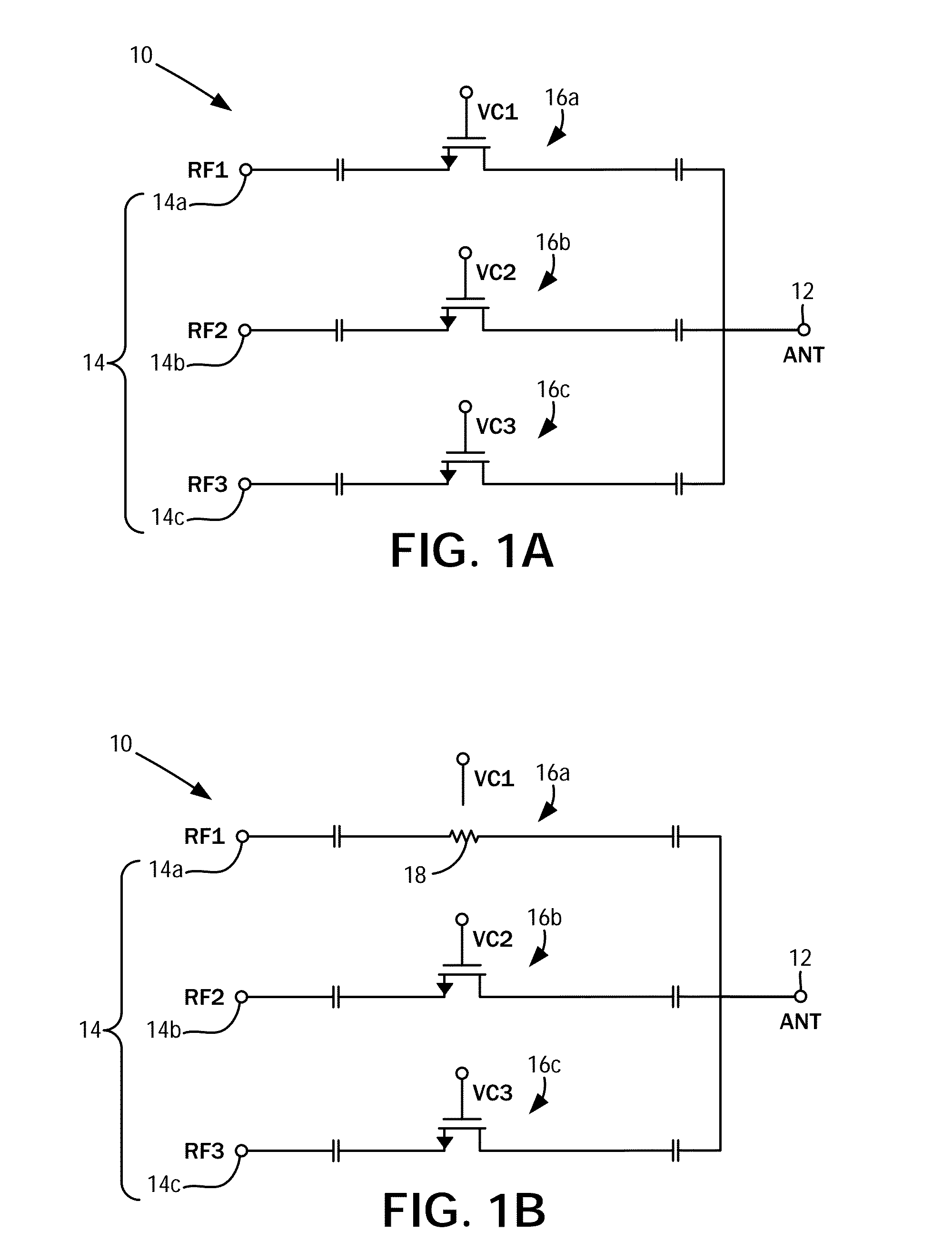
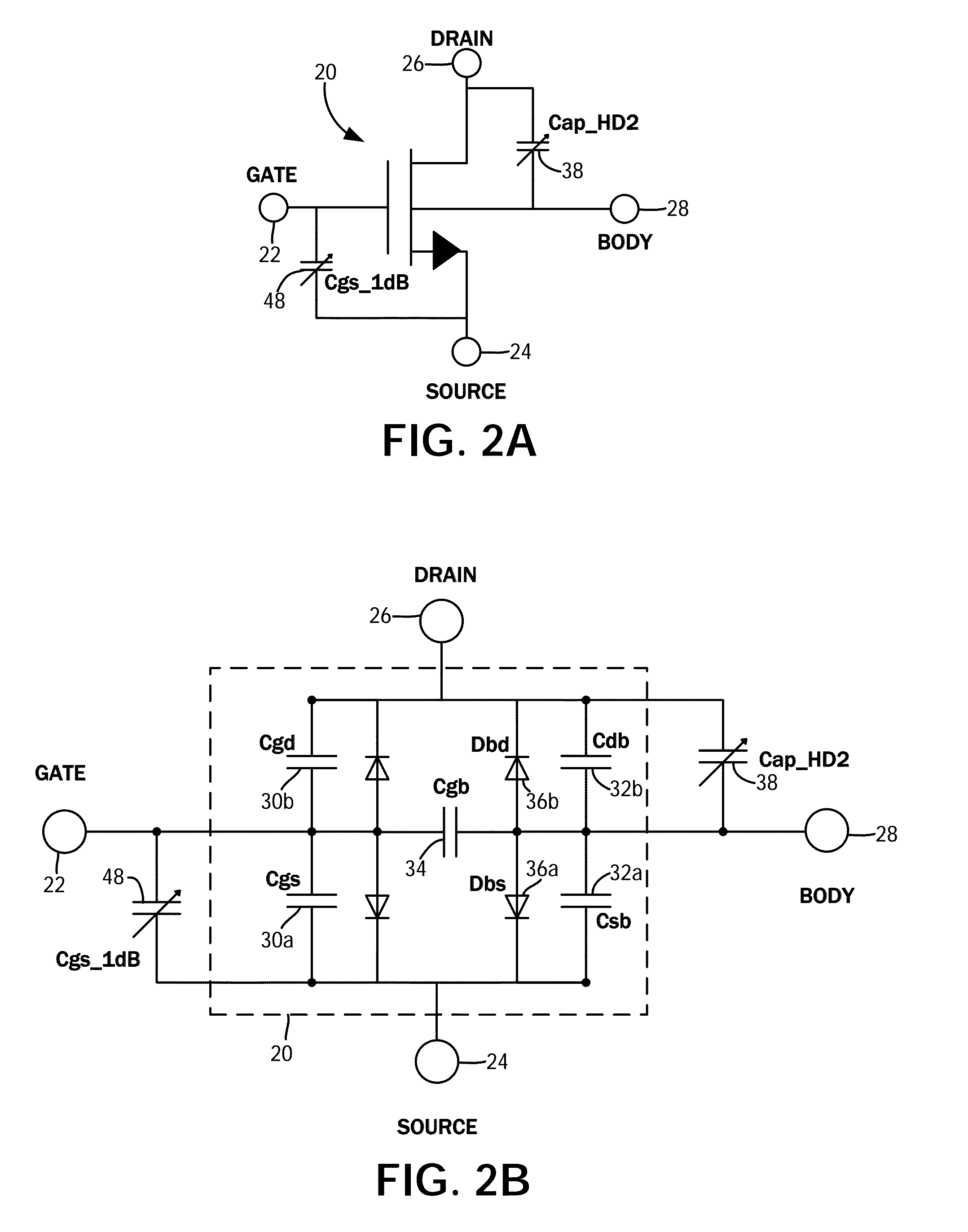
The present disclosure describes a RF switch circuit with improved harmonic suppression and low insertion loss. The circuit includes a plurality of transistor switch circuits, each containing a transistor, a harmonic suppression capacitor, and a parallel inductor. These circuits are connected to an antenna port and multiple signal ports. The transistors, when in an off state, form tank circuits that suppress RF signals from other circuits. The harmonic suppression capacitor is designed to distribute large signal voltage swings across the transistor. The circuit also includes a common pole terminal and multiple control line terminals, transistors, and inductors. These elements can be used to create a multi-pole multi-signal switch with excellent performance. The technical effects of the invention include improved harmonic suppression and low insertion loss.

Problems solved by technology

However, there is a performance tradeoff between insertion loss and harmonic distortion under large signal operation.
Furthermore, because of low mobility, low breakdown voltage, and high substrate conductivity associated with CMOS devices, an RF switch with low insertion loss, high isolation, wide bandwidth, and linearity is difficult to produce.
However, this is understood to result in a higher insertion loss because of the additional equivalent resistance of an “on” position.
Thus, insertion loss is higher than that of the stacked switches because of the resistance of three, as opposed to one transistor in the “on” state, and negatively impacts efficiency.

Method used


Image

  • Second order harmonic cancellation for radio frequency front-end switches
  • Second order harmonic cancellation for radio frequency front-end switches
  • Second order harmonic cancellation for radio frequency front-end switches

Examples


Embodiment Construction

[0028]The present disclosure encompasses various embodiments of a radio frequency (RF) switch that minimizes insertion loss while improving harmonics suppression. The detailed description set forth below in connection with the appended drawings is intended as a description of the several presently contemplated embodiments of the filter, and is not intended to represent the only form in which the disclosed invention may be developed or utilized. The description sets forth the functions and features in connection with the illustrated embodiments. It is to be understood, however, that the same or equivalent functions may be accomplished by different embodiments that are also intended to be encompassed within the scope of the present disclosure. It is further understood that the use of relational terms such as first and second and the like are used solely to distinguish one from another entity without necessarily requiring or implying any actual such relationship or order between such e...


PUM


Abstract

A radio frequency switch circuit with improved harmonic suppression and low insertion loss has an antenna port and a plurality of signal ports. A plurality of transistor switch circuits, are connected to a respective one of the plurality of signal ports and to the antenna port. Each of the transistor switch circuits has a transistor, which in an off state, together with a harmonic suppression capacitor and a parallel inductor both connected thereto, define a tank circuit that suppresses RF signals applied to the corresponding transistor switch circuit from a different one of the transistor switch circuits. The harmonic suppression capacitor is tuned to distribute large signal voltage swings in the RF signal amongst parasitic diodes of the transistor.

Description

CROSS-REFERENCE TO RELATED APPLICATIONS[0001]This application relates to and claims the benefit of U.S. Provisional Application No. 61 / 820,906, filed May 8, 2013 and entitled SECOND ORDER HARMONIC CANCELLATION FOR RADIO FREQUENCY FRONT END SWITCHES, the entirety of the disclosure of which is wholly incorporated by reference herein.STATEMENT RE: FEDERALLY SPONSORED RESEARCH / DEVELOPMENT[0002]Not ApplicableBACKGROUND[0003]1. Technical Field[0004]The present disclosure relates generally to radio frequency (RF) signal circuitry, and more particularly, to second order harmonic cancellation for switches in RF front end circuits.[0005]2. Related Art[0006]Complex, multi-function electronic devices are comprised of many interconnected modules and components, each of which serves a dedicated purpose. As a general example, wireless communication devices may be comprised of a transmit chain and a receive chain, with the antenna and the transceiver circuit being a part of both the transmit chain ...

Claims


Application Information

Patent Timeline
Patent Type & Authority Applications(United States)
IPC IPC(8): H04B1/44
CPCH04B1/44H04B1/48H04B2001/485
Inventor ZHAO, HUANLI, QIANG
Owner SKYWORKS SOLUTIONS INC
Learn More