
Arm for construction machine

a construction machine and arm technology, applied in the direction of cranes, lifting devices, constructions, etc., can solve the problem that the inner side of each side plate cannot be weldable, and achieve the effect of improving fatigue strength

Active Publication Date: 2014-11-13
NIHON KENKI CO LTD
View PDF9 Cites 13 Cited by
  • Summary
  • Abstract
  • Description
  • Claims
  • Application Information

AI Technical Summary

Benefits of technology

The present invention aims to provide an arm for a construction machine with improved fatigue strength and reduced weight. The invention achieves this by reducing stress concentration on non-welded parts formed in the corner parts where the plates intersect, and forming firm plates to prevent the formation of non-welded parts on joint parts between the plates. These improvements lead to a reduction in weight and an increase in fatigue strength of the arm, resulting in improved reliability of the entire arm. The invention also improves workability when welding the boom connecting boss to the side plates.

Problems solved by technology

That is, the fillet welding cannot be applied from the inner side of each of the side plates.

Method used


Image

  • Arm for construction machine
  • Arm for construction machine
  • Arm for construction machine

Examples


Embodiment Construction

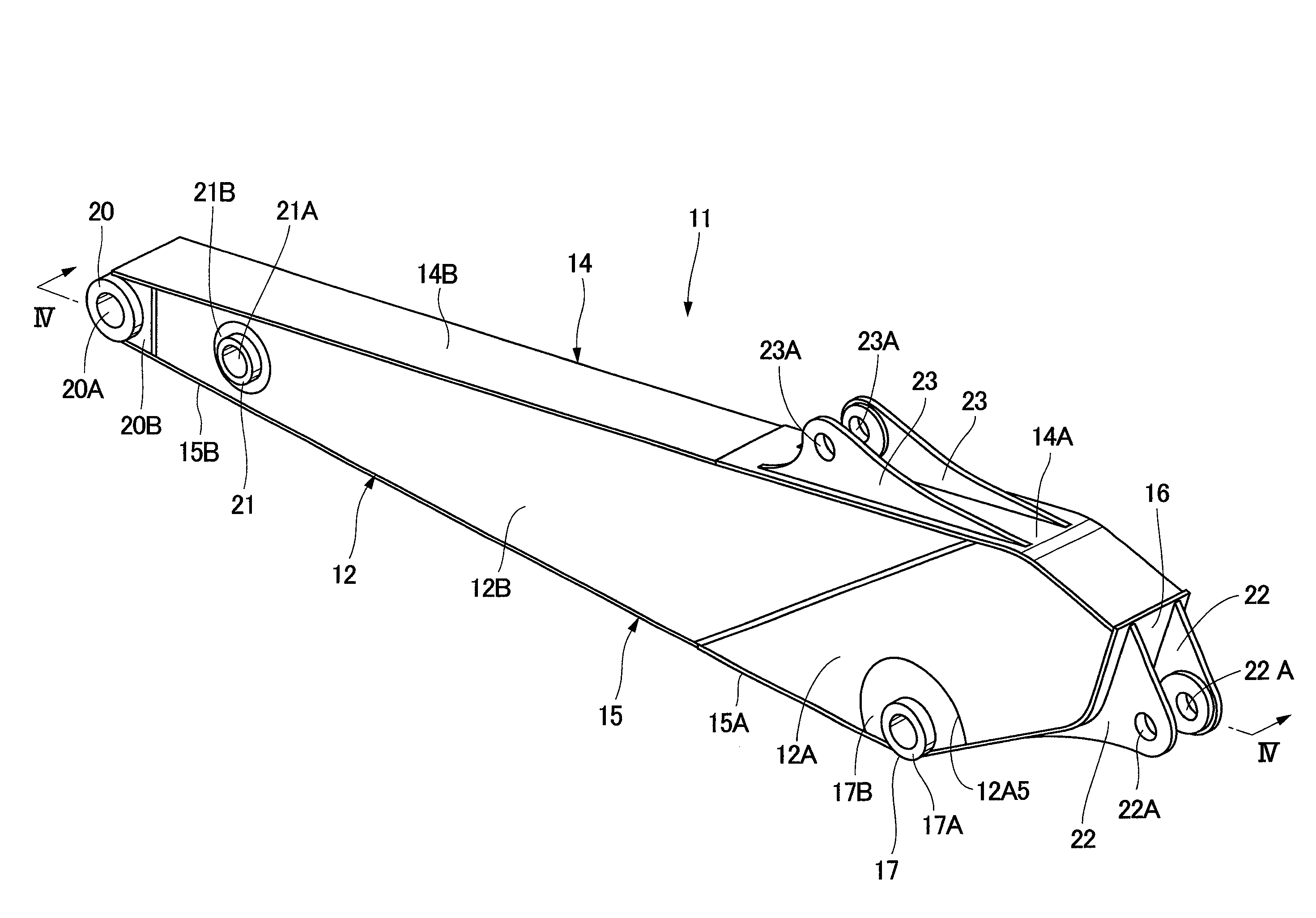
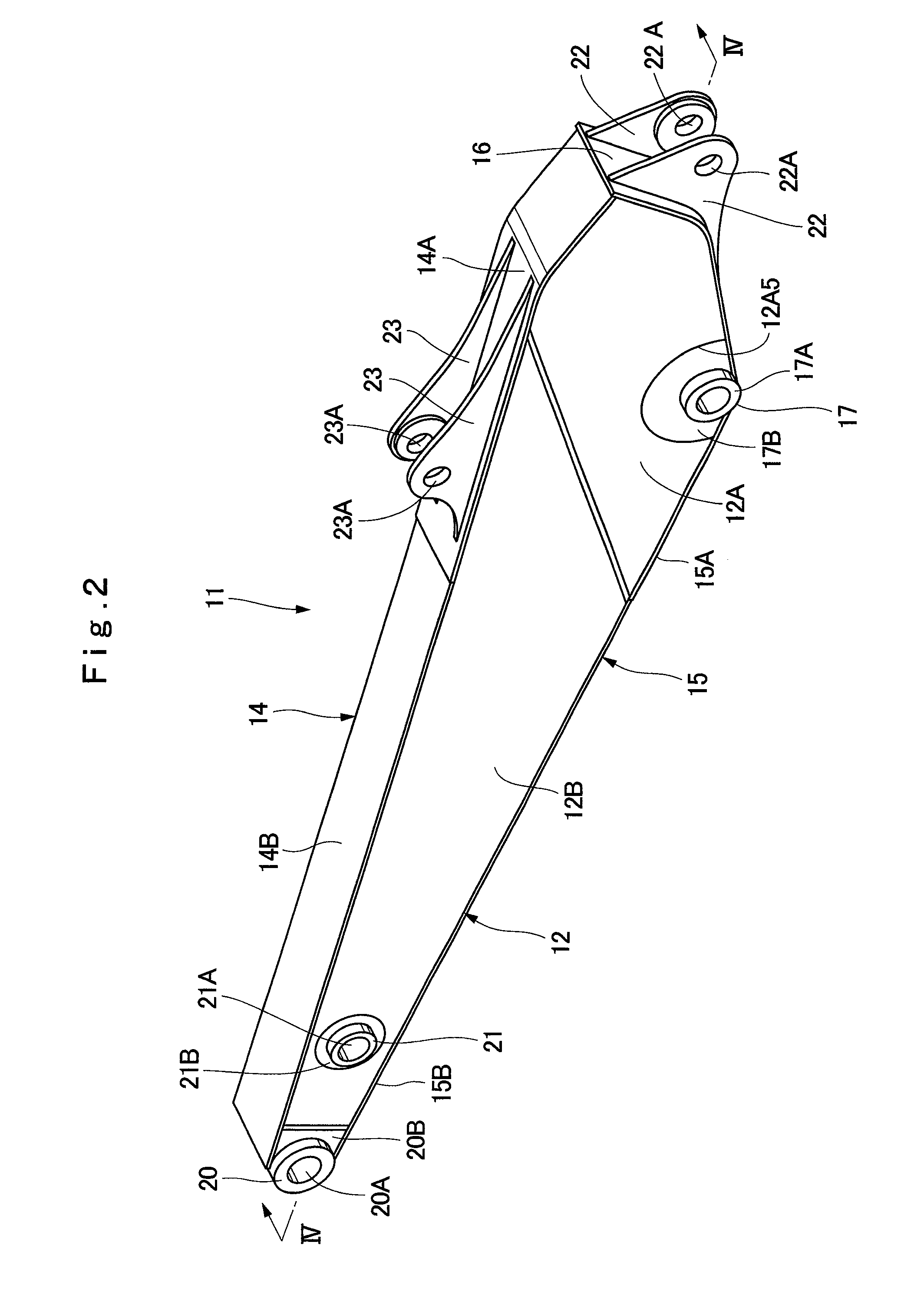
[0042]An embodiment of an arm for a construction machine according to the present invention will be described below in detail using a case in which it is applied to an arm of a hydraulic excavator as an example and by referring to the attached drawings.

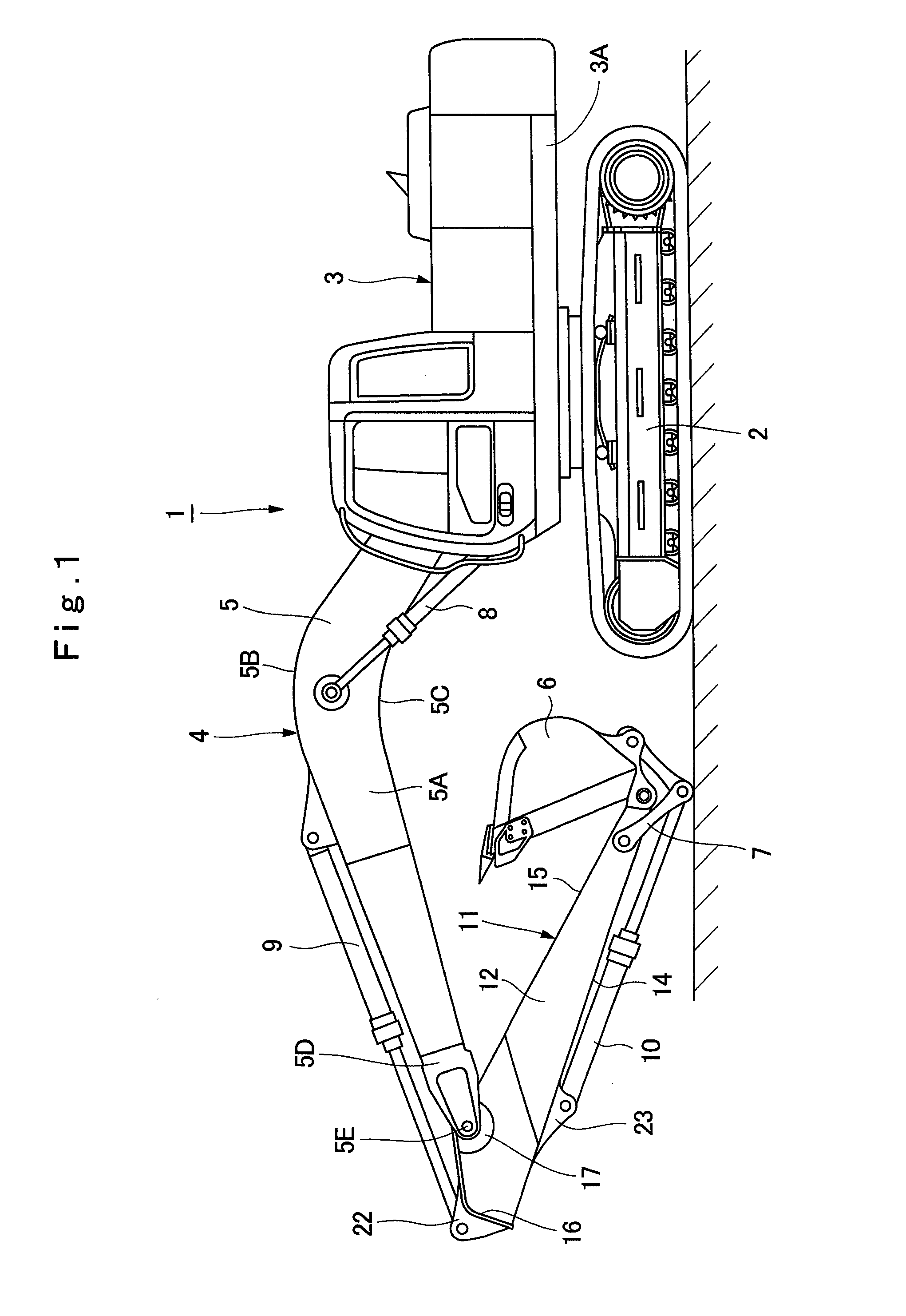
[0043]Designated at 1 is a hydraulic excavator as a typical example of a construction machine in the figure. The hydraulic excavator 1 is constituted by an automotive crawler-type lower traveling structure 2, an upper revolving structure 3 rotatably mounted on the lower traveling structure 2, and a working mechanism 4 tiltably provided on a front side of a revolving frame 3A which becomes a base of the upper revolving structure 3.

[0044]The working mechanism 4 is provided with a boom 5 having a base end portion tiltably pin-connected to the front side of the revolving frame 3A, an arm 11 which will be described later and has a base end portion rotatably pin-connected to a distal end portion of the boom 5, a bucket 6 rotatably pin-conne...


PUM


Abstract

In an arm for a construction machine formed as a box-shaped structural body by left and right side plates, an upper plate, a lower plate, and a rear plate, a left rear thick side plate constituting the left side plate, a right rear thick side plate constituting the right side plate, a rear thick upper plate constituting the upper plate, and a rear thick lower plate constituting the lower plate are formed by using a soft steel material having a large plate thickness. A left front thin side plate constituting the left side plate, a right front thin side plate constituting the right side plate, a front thin upper plate constituting the upper plate, and a front thin lower plate constituting the lower plate are formed by using a high tensile steel material having a small plate thickness. As a result, the weight of the entire arm can be reduced.

Description

TECHNICAL FIELD[0001]The present invention relates to an arm for a construction machine suitably used in a working mechanism mounted on a construction machine such as a hydraulic excavator and the like, for example.BACKGROUND ART[0002]In general, a hydraulic excavator which is a typical example of a construction machine is composed of an automotive lower traveling structure and an upper revolving structure rotatably mounted on the lower traveling structure. A working mechanism performing excavating work of earth and sand and the like is tiltably provided on the front side of a revolving frame constituting the upper revolving structure.[0003]Here, the working mechanism of a hydraulic excavator is composed mainly of a boom having the base end side rotatably mounted on the revolving frame, an arm rotatably mounted on the distal end side of the boom, a working tool such as a bucket or the like rotatably mounted on the distal end side of the arm, and a boom cylinder, an arm cylinder, and...

Claims


Application Information

Patent Timeline
Patent Type & Authority Applications(United States)
IPC IPC(8): E02F3/38
CPCE02F3/38E02F9/006
Inventor TAKAHASHI, TAKESHISHIMODAIRA, TAKAYUKITAKADA, RYUJISUGAYA, MAKOTO
Owner NIHON KENKI CO LTD
Learn More