Structure and method for self protection of power device with expanded voltage ranges
a power device and voltage range technology, applied in the direction of emergency protective circuit arrangement, solid-state device, etc., can solve the problems of unfavorable manufacturing and operation, increase in die size, and damage to other components
- Summary
- Abstract
- Description
- Claims
- Application Information
AI Technical Summary
Benefits of technology
Problems solved by technology
Method used
Image
Examples
Embodiment Construction
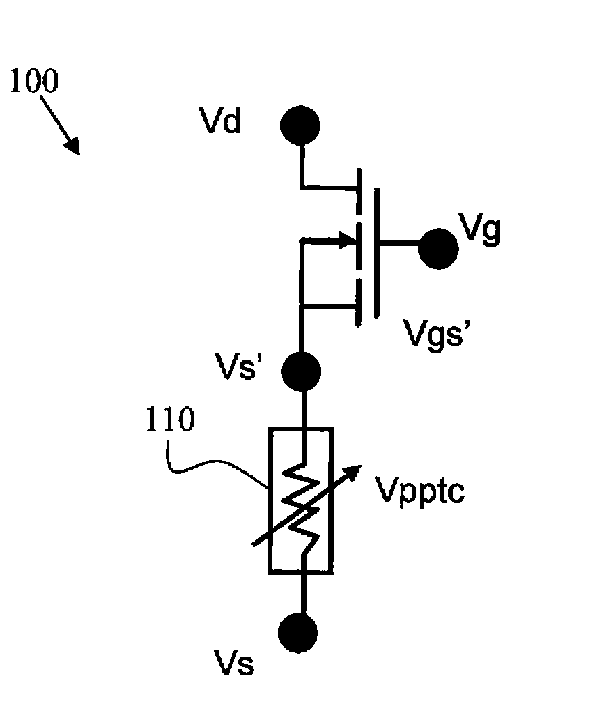
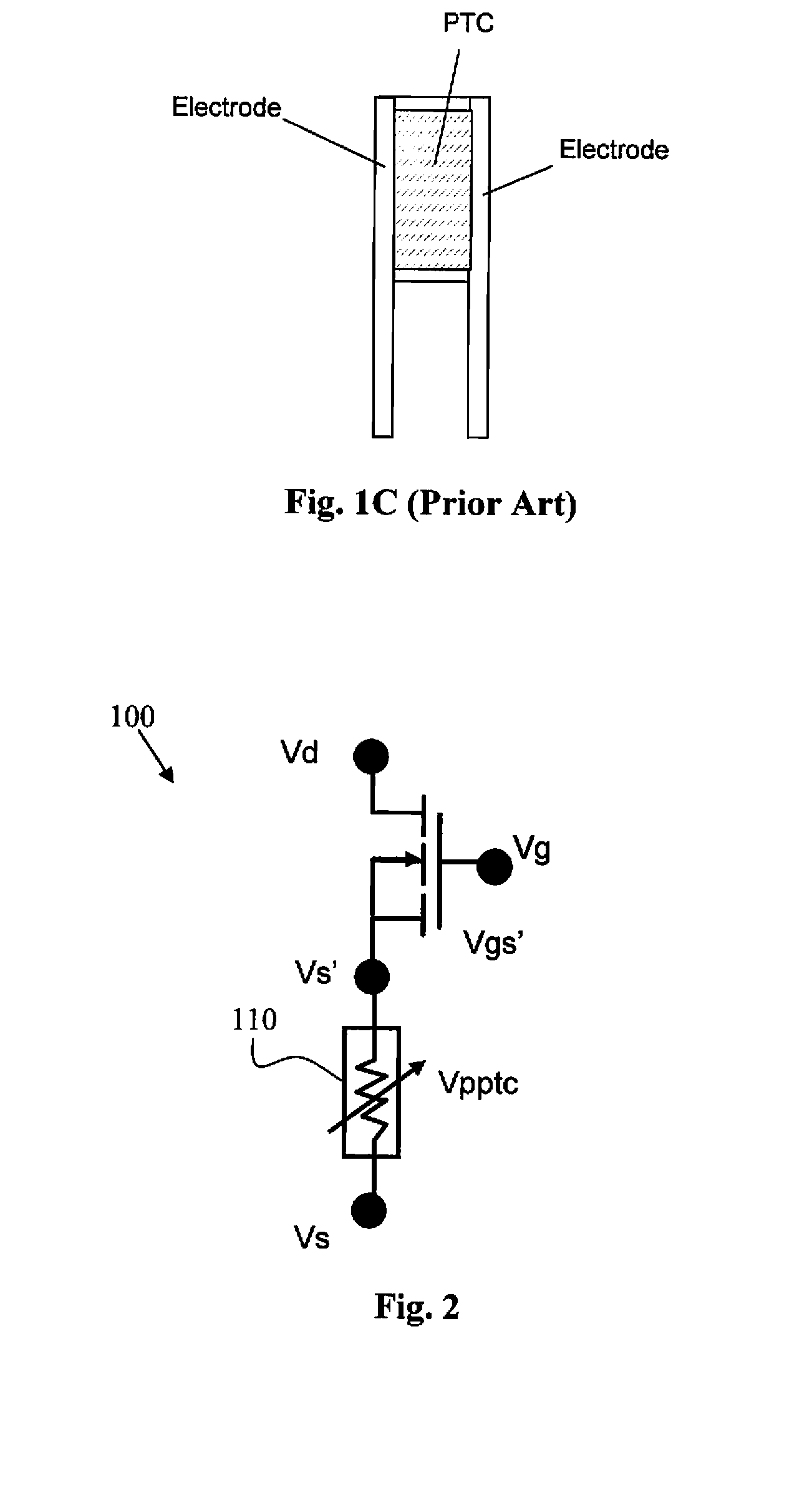
[0027]FIG. 2 is a schematic representation of a PTC protected FET 100, (which can also be referred to as a fuse FET) that includes a resistor 110 composed of a material, that has a positive temperature coefficient (FTC) and configured as a conductive layer connected to a source electrode and further provides a feedback voltage to regulate the gate-source voltage. As the temperature of the device under protection is increased, the resistance of the PTC resistor 110 is also increased and the resistance is drastically increased once the PTC trip temperature is reached. In this protection configuration, any source to drain current (Ids) increase will result in a voltage drop Vptc across the PTC structure 110 thus reducing the FET control voltage Vgs. Specifically, the voltages have functional relationships that can be represented as:
Vgs=Vgs′+Vptc
Vgs′=Vgs−Vptc
[0028]When the temperature of the device is above the trip temperature of the PTC, the voltage drop across the FTC structure Vpt...
PUM
 Abstract
Description
Claims
Application Information
 - R&D
- Intellectual Property
- Life Sciences
- Materials
- Tech Scout
- Unparalleled Data Quality
- Higher Quality Content
- 60% Fewer Hallucinations
Browse by: Latest US Patents, China's latest patents, Technical Efficacy Thesaurus, Application Domain, Technology Topic, Popular Technical Reports.
© 2025 PatSnap. All rights reserved.Legal|Privacy policy|Modern Slavery Act Transparency Statement|Sitemap|About US| Contact US: help@patsnap.com


