Differential pressure flow sensor

Active Publication Date: 2014-11-13
KONINKLJIJKE PHILIPS NV
View PDF2 Cites 10 Cited by
  • Summary
  • Abstract
  • Description
  • Claims
  • Application Information

AI Technical Summary

Benefits of technology

The present invention provides a device and method for measuring the differential pressure of gas between an inlet and an outlet in a flow body. The device includes a housing with a conduit between the inlet and outlet, and a flow body with a plurality of channels. The channels include primary, secondary, and tertiary channels. The device also includes means for establishing fluid communication with the primary and secondary channels, and generating output signals conveying information related to pressure and flow rate parameters of the gas. The device can measure the pressure of the gas at the inlet and outlet, and the flow of gas through the primary channels remains relatively constant across flow rates. The invention provides a more accurate and reliable means for measuring differential pressure in a flow body.

Problems solved by technology

Is it known that existing flow sensors have various restrictions and / or complications under certain operating conditions.

Method used


Image

  • Differential pressure flow sensor
  • Differential pressure flow sensor
  • Differential pressure flow sensor

Examples


Embodiment Construction

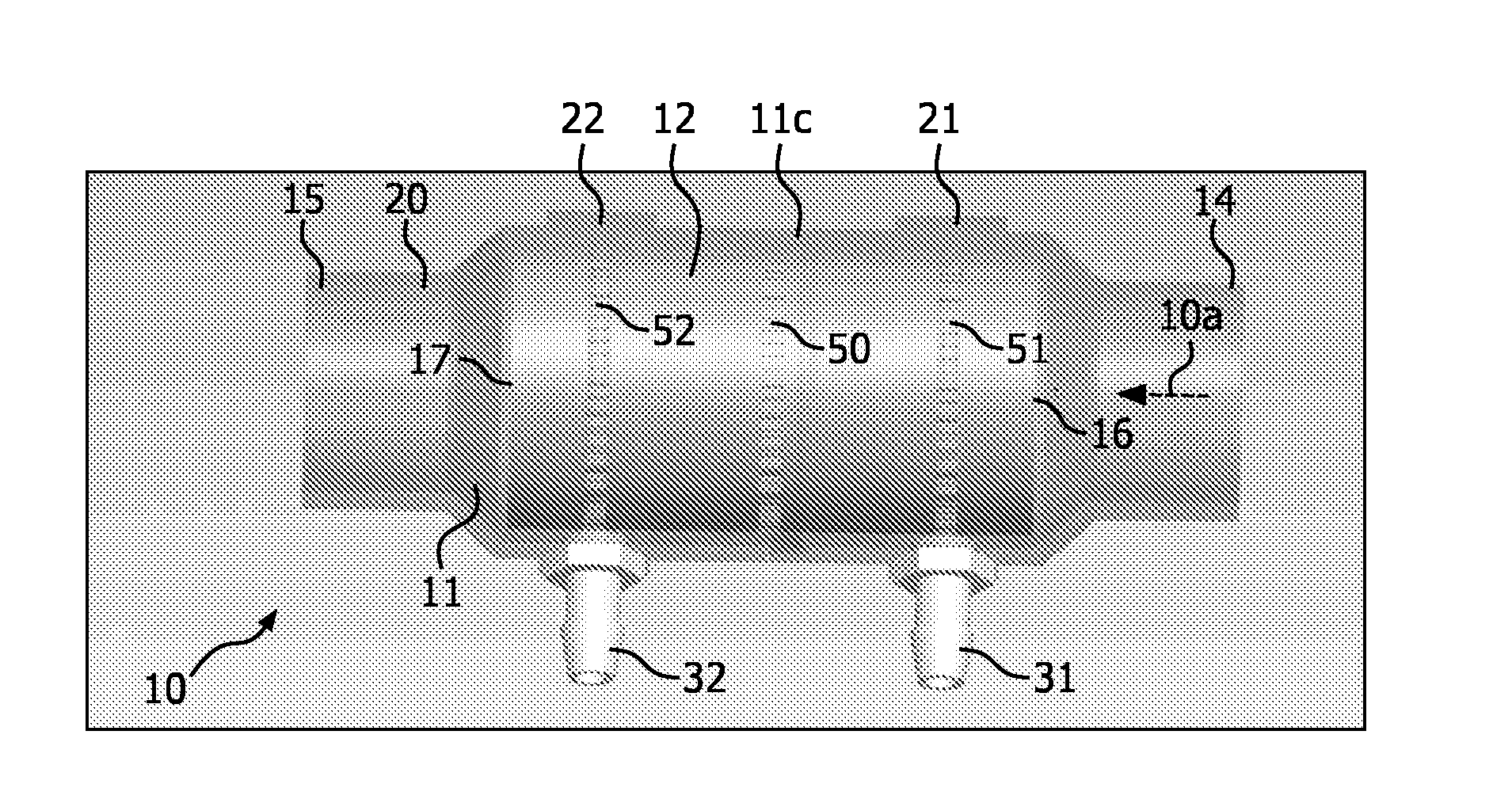
[0016]As used herein, the singular form of “a”, “an”, and “the” include plural references unless the context clearly dictates otherwise. As used herein, the statement that two or more parts or components are “coupled” shall mean that the parts are joined or operate together either directly or indirectly, i.e., through one or more intermediate parts or components, so long as a link occurs. As used herein, “directly coupled” means that two elements are directly in contact with each other. As used herein, “fixedly coupled” or “fixed” means that two components are coupled so as to move as one while maintaining a constant orientation relative to each other.

[0017]As used herein, the word “unitary” means a component is created as a single piece or unit. That is, a component that includes pieces that are created separately and then coupled together as a unit is not a “unitary” component or body. As employed herein, the statement that two or more parts or components “engage” one another shal...


PUM


Abstract

A differential pressure flow sensor that includes a plurality of channels divided into multiple sets of channels having different characteristics. Primary channels establish fluid communication between an inlet and an outlet of the flow sensor. Secondary channels establish fluid communication between the inlet and a first pressure port, but not the outlet. Tertiary channels establish fluid communication between the outlet and a second pressure port, but not the inlet. Signals generated at the first and second pressure port are used to determine a rate of flow through of gas through the sensor. Due to the structural features of the device, the phase delay of individual oscillatory flow components compared to corresponding oscillatory pressure components remains substantially constant across a wide range of flow rates.

Description

CROSS-REFERENCE TO RELATED APPLICATIONS[0001]This patent application claims the priority benefit under 35 U.S.C. §119(e) of U.S. Provisional Application No. 61 / 569,486 filed on Dec. 12, 2011, the contents of which are herein incorporated by reference.BACKGROUND OF THE INVENTION[0002]1. Field of the Invention[0003]The present disclosure pertains to systems and methods for measuring a differential pressure of a flow of gas and / or liquid in a flow body and, in particular, for measuring a differential pressure of an oscillatory flow.[0004]2. Description of the Related Art[0005]It is well known that some types of respiratory therapy involve the delivery of a pressurized flow of breathable gas to the airway of a subject. It is known that providing high-quality respiratory therapy, through a ventilator and / or pressure support device, hinges on accurately measuring the flow and / or (differential) pressure of a pressurized flow of breathable gas. Is it known that existing flow sensors have va...

Claims


Application Information

Patent Timeline
IPC IPC(8): G01F1/34G01N33/497G01F1/40
CPCG01F1/34G01F1/40G01N33/497A61B5/087G01F1/48A61M16/0051A61M2016/0027A61M2016/0036A61M2205/3375A61M2205/505A61M2205/52A61M2205/581A61M2205/582A61M2205/583A61M16/101A61M16/0858A61M16/024
Inventor ROMANO, ROBERT
Owner KONINKLJIJKE PHILIPS NV
Why Eureka
Try Eureka