Novel secondary structure of carbon nanostructure, bundle thereof and composite comprising same
a carbon nanotube and secondary structure technology, applied in the direction of carbonsing rags, yarn, transportation and packaging, etc., can solve the problems of many limits on industrial adaptation or application, the primary structure of carbon nanotubes cannot be directly controlled to the actual standard enough for industrial application, and the productivity of carbon nanotubes is very low
- Summary
- Abstract
- Description
- Claims
- Application Information
AI Technical Summary
Benefits of technology
Problems solved by technology
Method used
Image
Examples
example 1
Synthesis of AlO(OH)
[0100]Al(O-sec-Bu)3 50 g was mixed with EtOH 25 ml, and stirred at 120° C. for 30 min, and then distilled water 15 ml was added thereto followed by cooling to room temperature. The cooled product was filtered using a glass filter to obtain precipitate, and the precipitate was washed with acetone several times, and then dried at 120° C. for 3 hrs to obtain AlO(OH).
[0101]
[0102]The synthesized AlO(OH) was ball-milled using a zirconia ball at 200 to 250 rpm. The milling processed AlO(OH) support was 0.3 μm in particle size (d50).
[0103]
[0104]Co(NO3)2.6H2O 870 mg and (NH4)6Mo7O24 120 mg were completely dissolved in distilled water 50 ml, and then the milling processed AlO(OH) 1.0 g was added thereto followed by mixing at 60° C., 85 mb for 30 min and then at 10 mb for 30 min to obtain a supported catalyst precursor in solid phase. The obtained supported catalyst precursor was dried at 120° C. for 1 hr, crushed and calcined at 600° C. for 4 hrs to obtain a supported cata...
examples 2 and 3
Preparation of Support
[0109]Al(OH)3 and gamma-Al2O3, which were heat-treated at 400° C., were ball-milled using a zirconia ball at 200 to 250 rpm, respectively. The milling-processed Al(OH)3 support and gamma-Al2O3 were 0.250 μm and 0.265 μm in particle diameter (d50), respectively.
[0110]
[0111]The procedure of Example 1 was repeated except for using the milling-processed Al(OH)3 and gamma-Al2O3, respectively (Example 2 and 3 in order), instead of using the AlO(OH), and therefore, 1.1 g and 1.2 g of supported catalysts were prepared.
[0112]
[0113]The procedure of Example 1 was repeated except for using a different supported catalyst to synthesize CNTs, and therefore CNT secondary structure bundles were manufactured in the reaction yields of 2,280% and 2,450%, respectively.
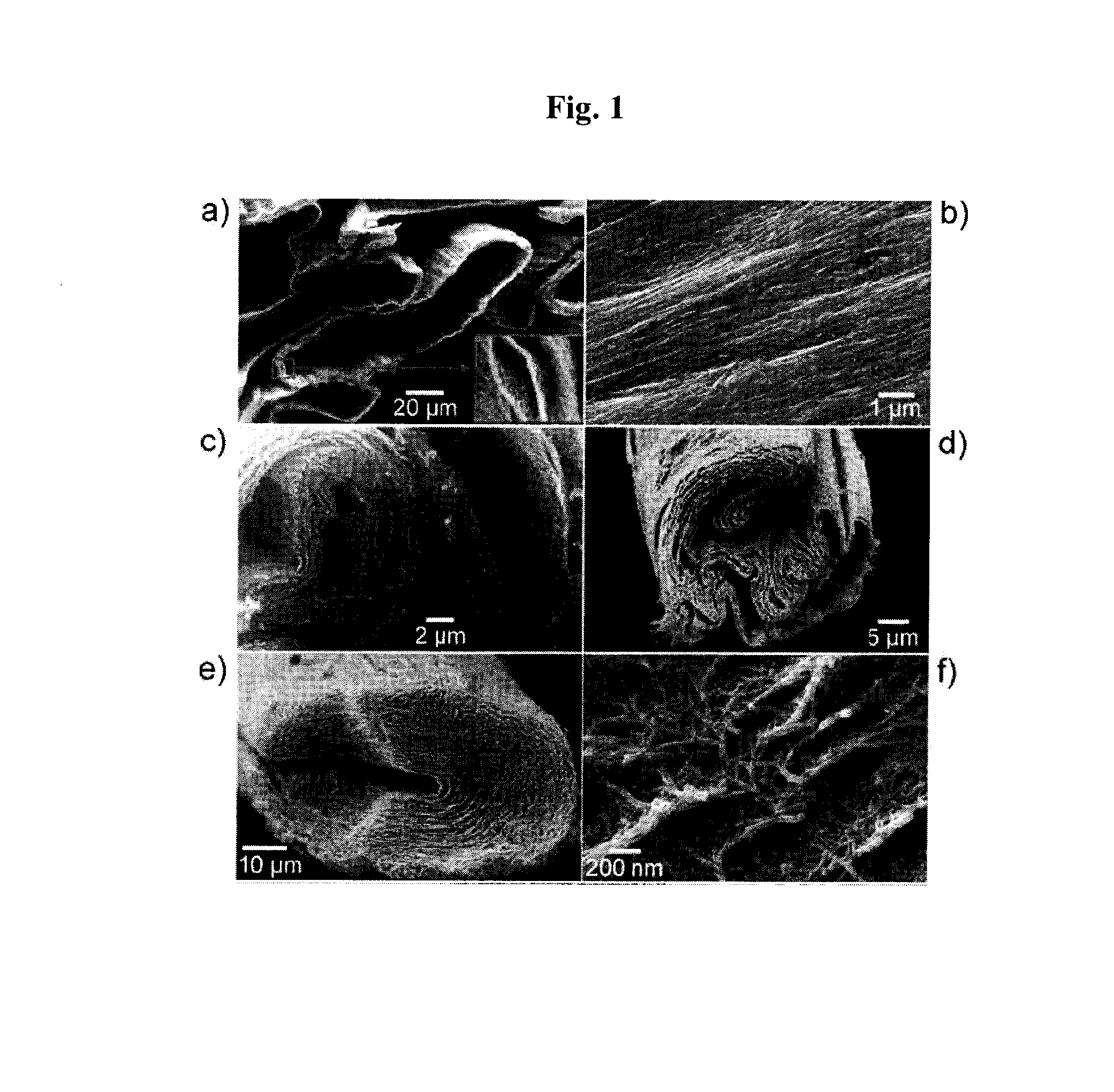
[0114]SEM images of each of the manufactured CNS secondary structure bundle were illustrated in FIG. 8.
[0115]As shown in FIG. 8, it was confirmed that the CNT secondary structure bundles manufactured by using the ball...
examples 4 to 12
[0116]The procedure of Example 1 was repeated except for using each of the supported catalysts calcined at 300, 400, 500, 550, 625, 650, 675, 700 and 750° C., respectively to manufacture CNT secondary structure bundles in the reaction yields of 1,664%, 1,921%, 2,245%, 2,074%, 2,015%, 2,065%, 2,100%, 2,300% and 2,464%, respectively.
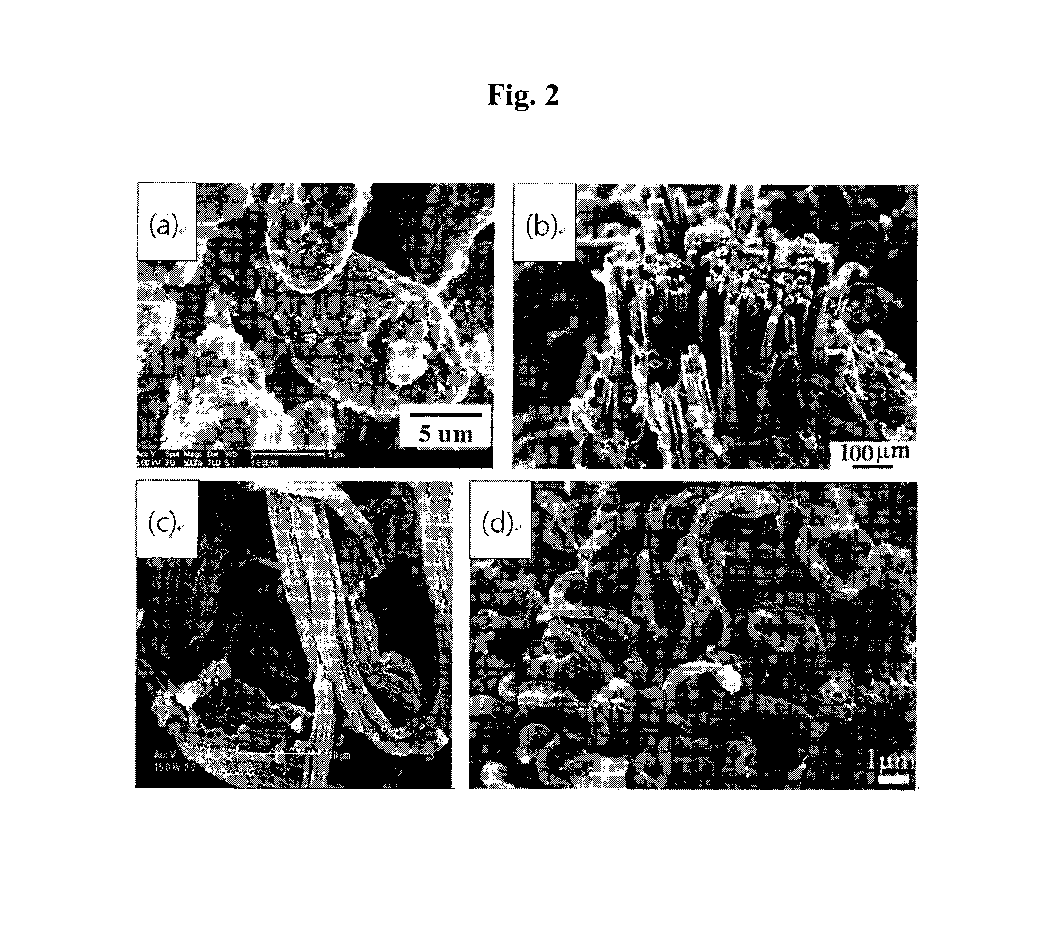
[0117]SEM images of each of the manufactured CNS secondary structure bundle were illustrated in FIG. 9.
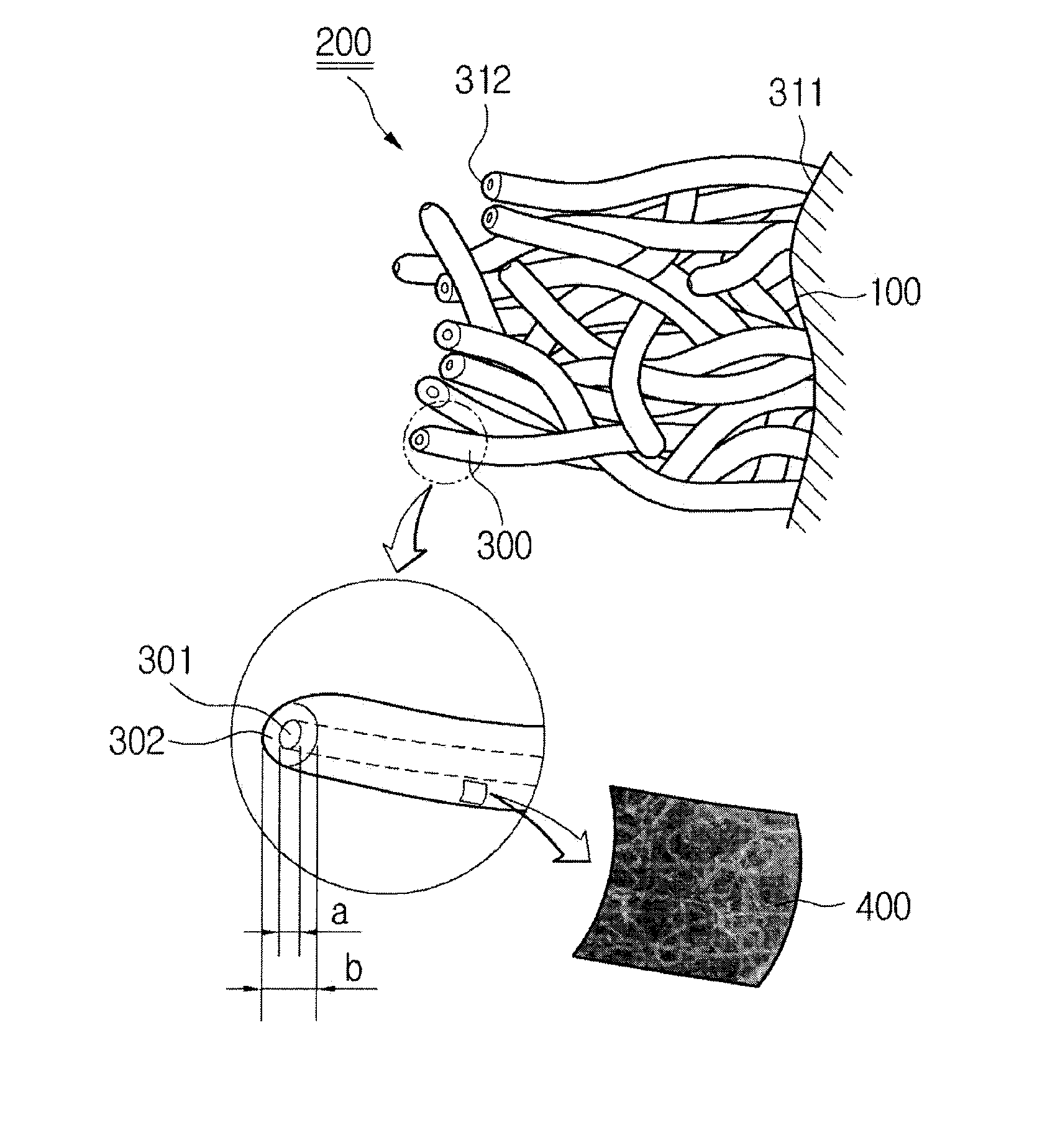
[0118]As shown in FIG. 9, it was confirmed that the CNT secondary structure bundles manufactured are new type bundles consisting of new type CNT secondary structures, in which pores as the center part are formed in the CNT secondary structures.
PUM
| Property | Measurement | Unit |
|---|---|---|
| internal diameter | aaaaa | aaaaa |
| diameter | aaaaa | aaaaa |
| diameter | aaaaa | aaaaa |
Abstract
Description
Claims
Application Information
 - R&D
- Intellectual Property
- Life Sciences
- Materials
- Tech Scout
- Unparalleled Data Quality
- Higher Quality Content
- 60% Fewer Hallucinations
Browse by: Latest US Patents, China's latest patents, Technical Efficacy Thesaurus, Application Domain, Technology Topic, Popular Technical Reports.
© 2025 PatSnap. All rights reserved.Legal|Privacy policy|Modern Slavery Act Transparency Statement|Sitemap|About US| Contact US: help@patsnap.com


