
Freeze prevention arrangement for pcv channel and intake manifold

Active Publication Date: 2014-11-06
AISIN SEIKI KK
View PDF8 Cites 38 Cited by
  • Summary
  • Abstract
  • Description
  • Claims
  • Application Information

AI Technical Summary

Benefits of technology

The invention relates to an intake manifold for an engine that prevents water in blowby gas from freezing and blocking the PCV channel. The technical effects of the invention include improving heat transfer from the EGR channel to the blowby gas, preventing freezing of the blowby gas, and reducing complexity and cost by utilizing a common channel as the heating portion. Additionally, the invention allows for the formation of an intake manifold with the PCV channel and EGR channel formed integrally with resin, reducing assembly steps and costs.

Problems solved by technology

However, not all of the mixture gas introduced to the combustion chamber is combusted.

Method used


Image

  • Freeze prevention arrangement for pcv channel and intake manifold
  • Freeze prevention arrangement for pcv channel and intake manifold
  • Freeze prevention arrangement for pcv channel and intake manifold

Examples


first embodiment

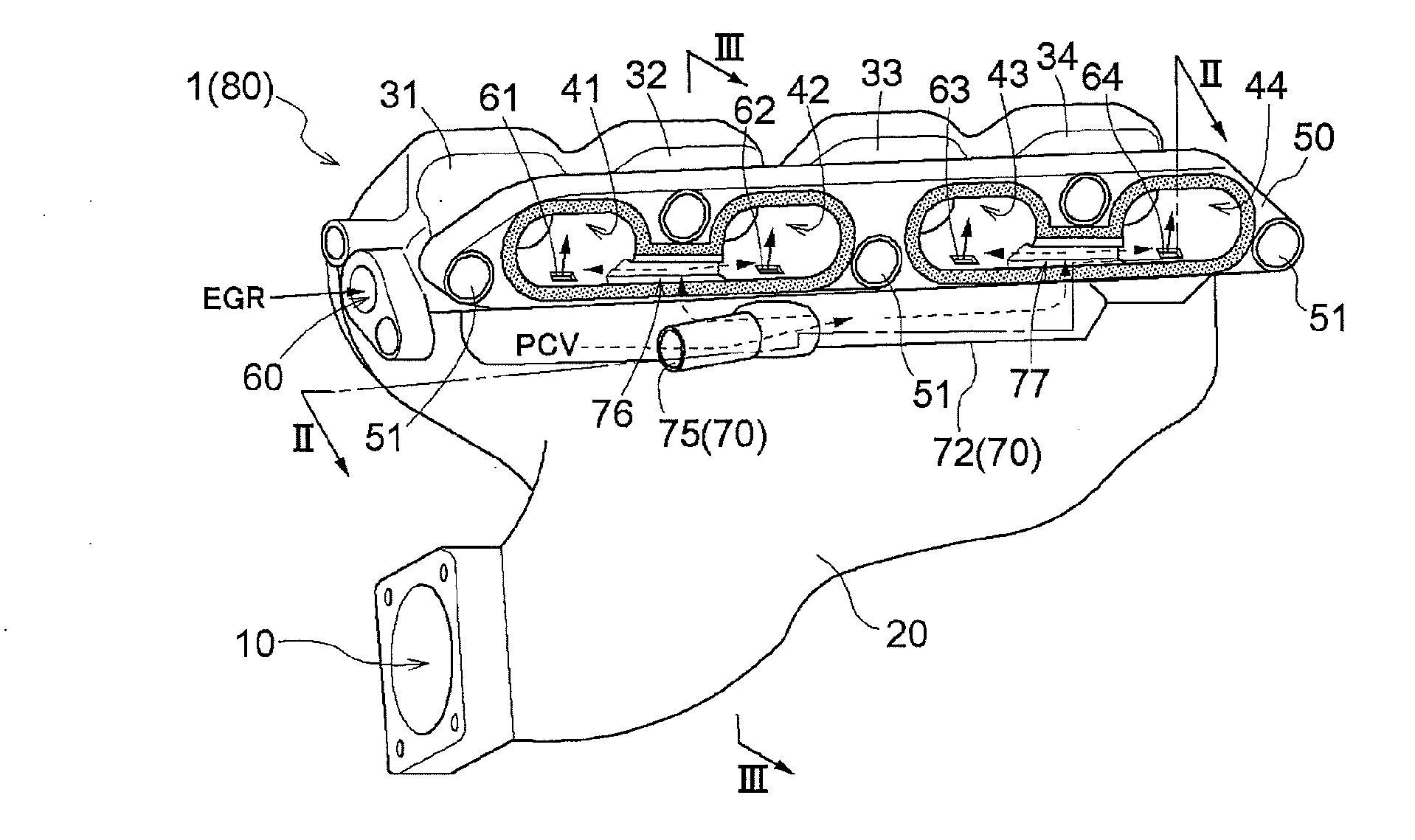
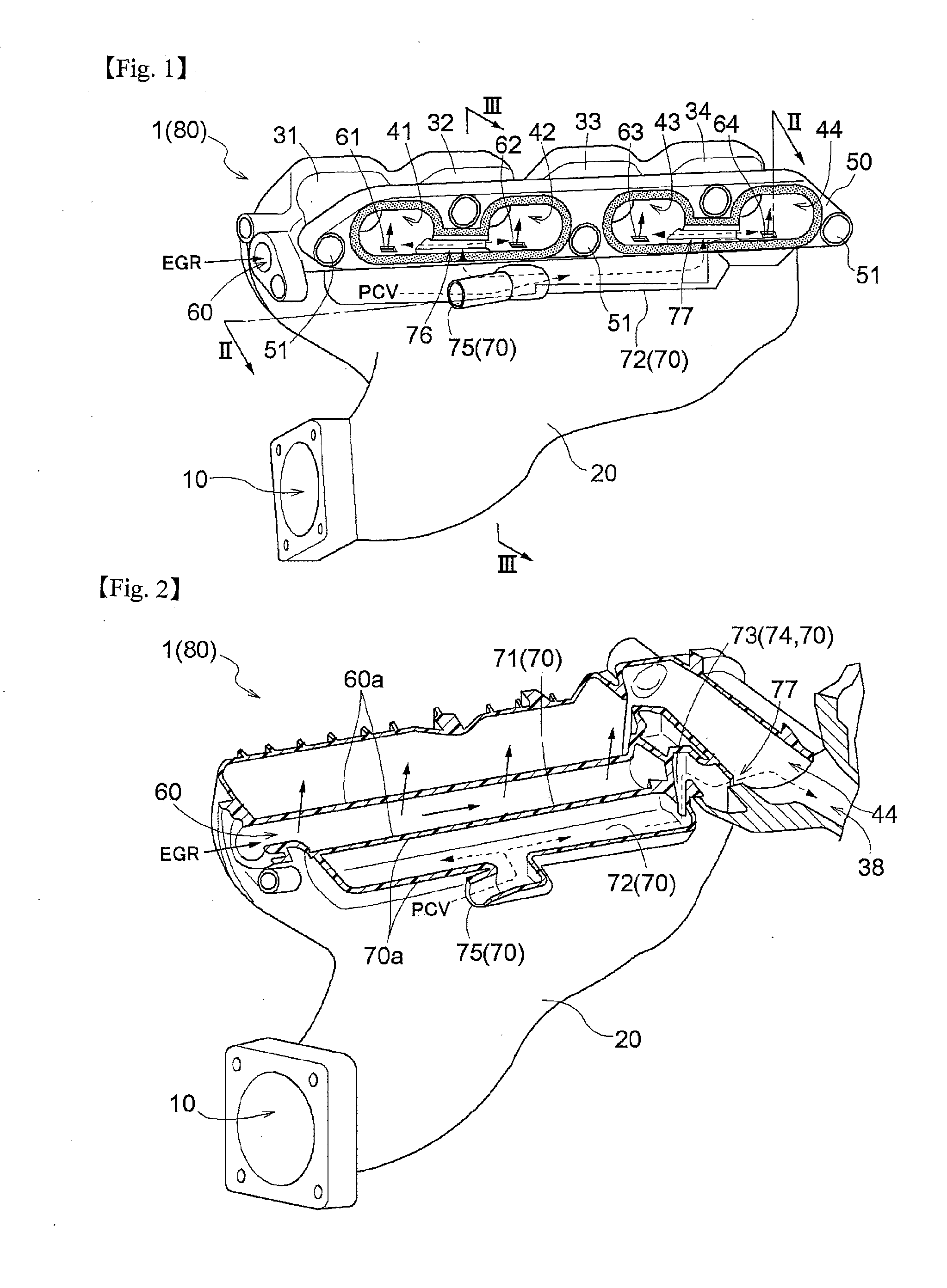
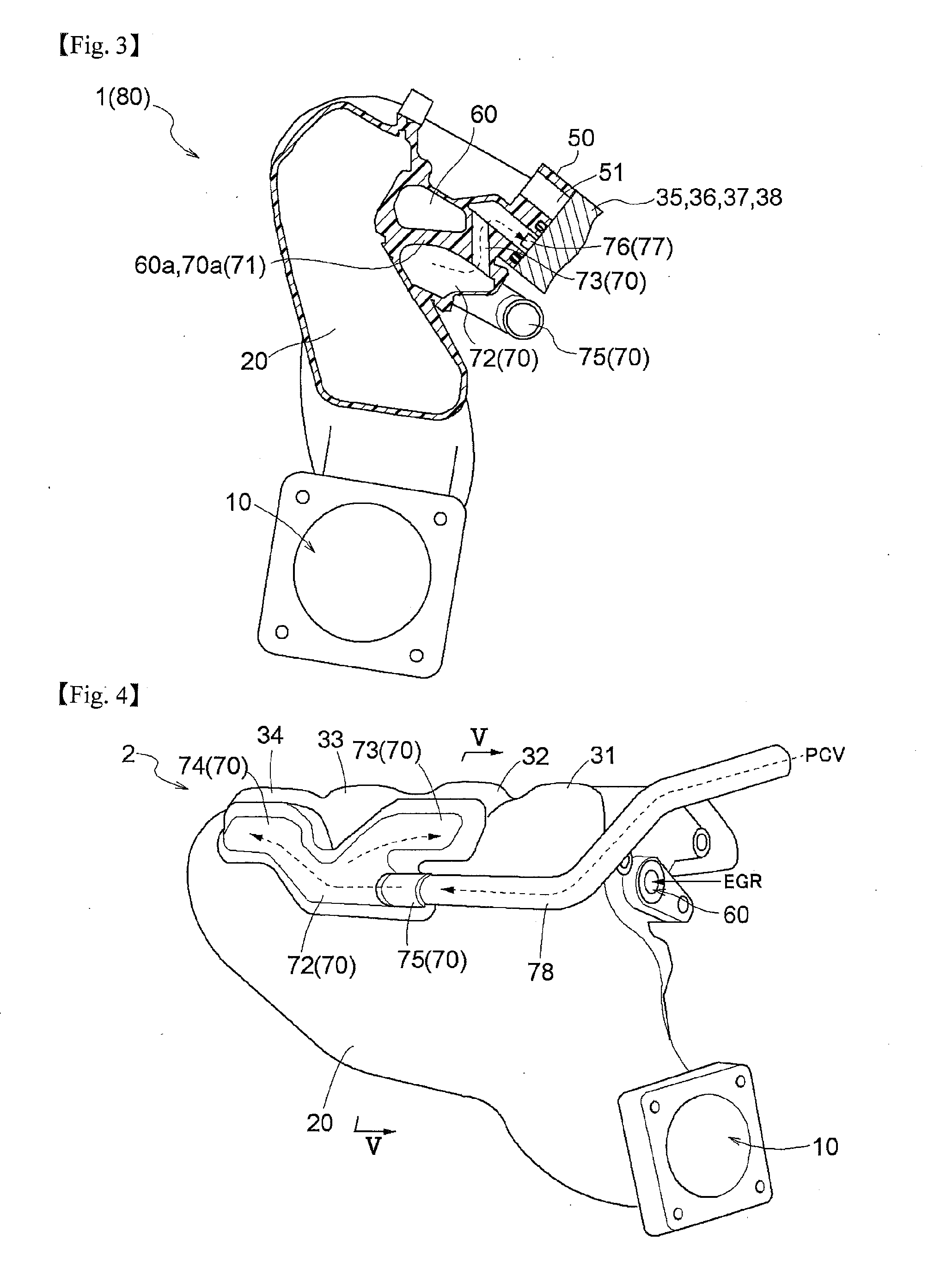
[0029]Next, embodiments of the present invention will be described in details with reference to the drawings. FIG. 1 is a perspective view showing an outer appearance of an intake having a freeze prevention arrangement for a PCV channel relating to a first embodiment. FIG. 2 is a section view taken along a line II-II in FIG. 1. FIG. 3 is a section view taken along a line III-III in FIG. 1.

[0030]An intake manifold 1 is used in an inline four-cylinder engine 80 (this may be referred to also as “engine 80” hereinafter). The intake manifold 1 is formed integral of a synthetic resin. As this synthetic resin, in consideration to such factors as strength, weight, moldability, etc., a synthetic resin comprised of a mixture of polyamide resin (PA6) and glass fiber is used for example. The principal function of the intake manifold 1 is to distribute air to the respective cylinders evenly. Air is suctioned through the intake manifold 1 into a respective combustion chamber due to a negative pre...

second embodiment

[0047]Next, a second embodiment of the present invention will be explained in details with reference to the drawings. FIG. 4 is a perspective view showing an outer appearance of an intake manifold 2 having a freeze prevention arrangement for a PCV channel relating to the second embodiment. FIG. 5 is a section view taken along a line V-V in FIG. 4. In the following, in the instant embodiment, substantially identical arrangements as those of the first embodiment will be denoted with same reference marks and explanation thereof will be omitted.

[0048]What makes this embodiment differs most from the first embodiment is the position of the PCV channel 70. As shown in FIG. 4 and FIG. 5, the PCV channel 70 in the instant embodiment is disposed on the outer side (this may be referred to as “the back side” also) of the curves of the intake channels 31-34. The EGR channel 60 is disposed on the inner side of the curves of the intake channels 31-34, just like the first embodiment. As the mountin...


PUM

PropertyMeasurementUnit
Lengthaaaaaaaaaa

Abstract

Provided are an arrangement capable of reliably preventing freeze of a PCV channel without requiring additional piping and an intake manifold having this arrangement. This arrangement for freeze prevention of a PCV channel includes a PCV channel returning blowby gas containing un-combusted fuel gas as a main component thereof and leaked into an engine to an intake port, an EGR channel returning exhaust gas exhausted from the engine to the intake port, and a heating portion as a common portion between a PCV outer wall of the PCV channel and an EGR outer wall of the EGR channel.

Description

TECHNICAL FIELD[0001]The present invention relates to a freeze prevention arrangement for a PCV channel in which blowby gas flows and also to an intake manifold having the freeze prevention arrangement.BACKGROUND ART[0002]An engine obtains power by rotation of a crankshaft caused by combustion of mixture gas in a combustion chamber. However, not all of the mixture gas introduced to the combustion chamber is combusted. A portion of the mixture gas leaks through a gap between a piston and a cylinder into a crankcase. This leaked gas is called blowby gas. Blowby gas as un-combusted fuel gas contains air pollutant in a high concentration. Therefore, discharging it as it is as an exhaust gas into the atmosphere is legally prohibited. Accordingly, an arrangement is provided for returning blowby gas to an intake port side via a PCV (Positive Crankcase Ventilation) channel, so that it is combusted with an amount of newly supplied mixture gas in the combustion chamber and then discharged int...

Claims


Application Information

Patent Timeline
IPC IPC(8): F01M13/00F02M31/135
CPCF01M13/0011F02M31/135F01M2013/0027F01M13/00F02M35/10222F02M35/10268F02M35/10321F02M35/112F02M25/06F02M31/0815F02M26/41Y02T10/12
Inventor SENDA, TOMOHISATERAMOTO, HIDEAKI
Owner AISIN SEIKI KK
Learn More