Dielectric dryer drum
a dryer drum and dielectric technology, applied in drying machines, lighting and heating apparatus, furnaces, etc., can solve problems such as problems in using a microwave oven as a dryer (basically the method used by ben-shmuel) and achieve the effects of uniform water removal, sufficient heating energy, and improved heating energy penetration
- Summary
- Abstract
- Description
- Claims
- Application Information
AI Technical Summary
Benefits of technology
Problems solved by technology
Method used
Image
Examples
first embodiment
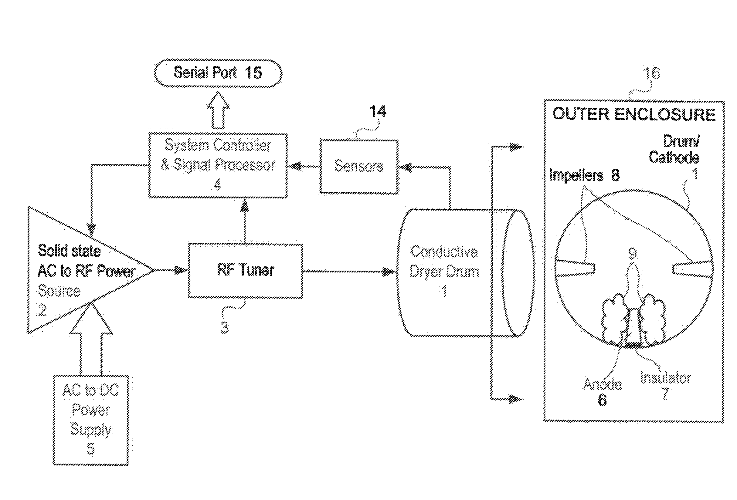
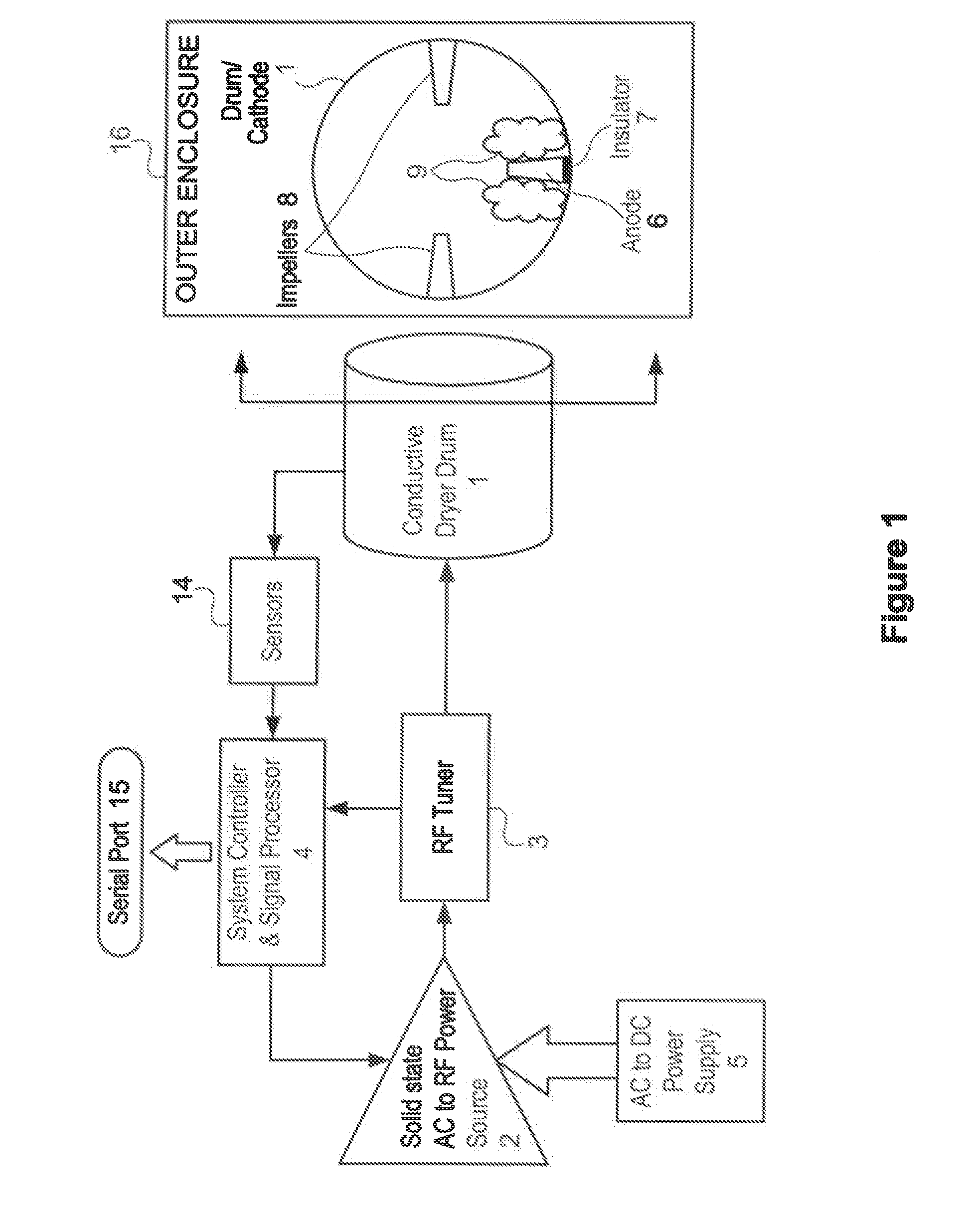
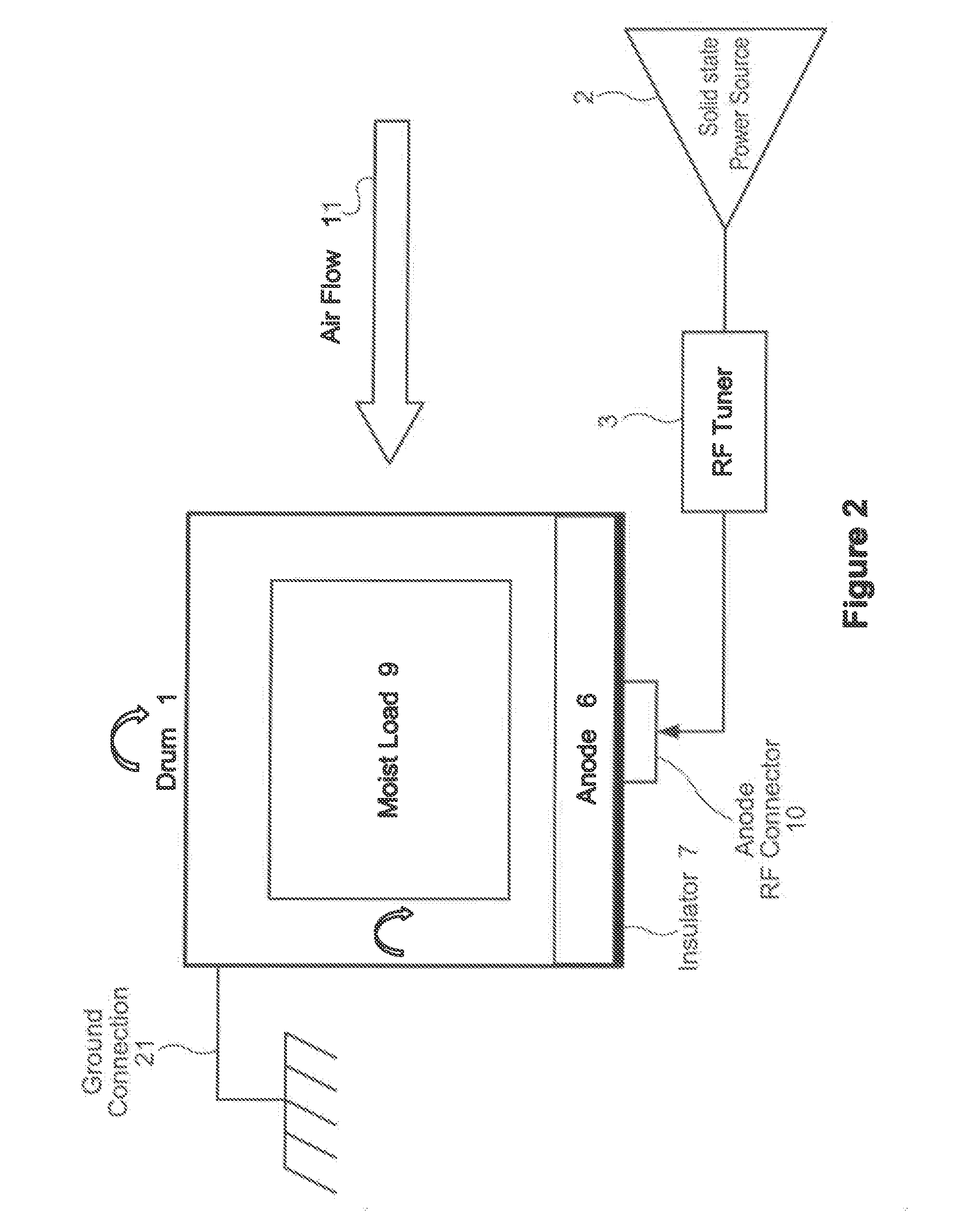
[0067]In a first embodiment, the anode 6 is coupled to the RF tuner 3 by using a fixed contact brush 204 that is coupled to tuner 3 and makes contact with a rotating brush commutator 202 that is coupled to the rotating anode 6, as shown in FIG. 6(a).
second embodiment
[0068]In a second embodiment, shown in FIG. 6(b), anode 6 is coupled to the RF source 2 and tuner 3 via a capacitive disc coupler comprising three axially aligned discs 208, 209, 210. In this embodiment, the inner (rightmost) disc 208 rotates and is coupled to the anode 6, the center disc 209 is an insulator, and the outer (leftmost) disc 210 is stationary and coupled to tuner 3.
third embodiment
[0069]In a third embodiment, anode 6 is coupled to RF source 2 and tuner 3 via a single capacitive cylinder disc coupler, as shown in FIG. 6(c). In this embodiment, the inner (rightmost) cylinder 214 is rotating and connected to anode 6, dielectric spacer 216 radially surrounds cylinder 214 and is an insulator, and the outer (leftmost) disc 212 is stationary and coupled to tuner 3.
[0070]FIG. 7 illustrates an embodiment of the present invention in which variable anode element coupling is employed to implement the capacitive disc coupler of FIG. 6(b). The coupling comprises three concentric plates: fixed plate 210, insulator 209, and rotating plate 208, as shown in the FIG. 7(b) side view and in FIG. 6(b). Typically, only a portion 222 of fixed plate 210 needs to be electrically conductive, as shown in the FIG. 7(a) rear view. Conductive capacitor plate 232 is attached to the anode 6, as shown in the FIG. 7(d) side view. FIG. 7(c) is a front view showing a typical location for plate 2...
PUM
 Abstract
Description
Claims
Application Information
 - R&D
- Intellectual Property
- Life Sciences
- Materials
- Tech Scout
- Unparalleled Data Quality
- Higher Quality Content
- 60% Fewer Hallucinations
Browse by: Latest US Patents, China's latest patents, Technical Efficacy Thesaurus, Application Domain, Technology Topic, Popular Technical Reports.
© 2025 PatSnap. All rights reserved.Legal|Privacy policy|Modern Slavery Act Transparency Statement|Sitemap|About US| Contact US: help@patsnap.com


