Computer system, data management method, and program
a computer system and data management technology, applied in computing, electric digital data processing, instruments, etc., can solve the problems of increasing processing costs, reducing and inflexible handling of temporary load changes, so as to maintain the performance of the entire system
- Summary
- Abstract
- Description
- Claims
- Application Information
AI Technical Summary
Benefits of technology
Problems solved by technology
Method used
Image

Examples
first embodiment
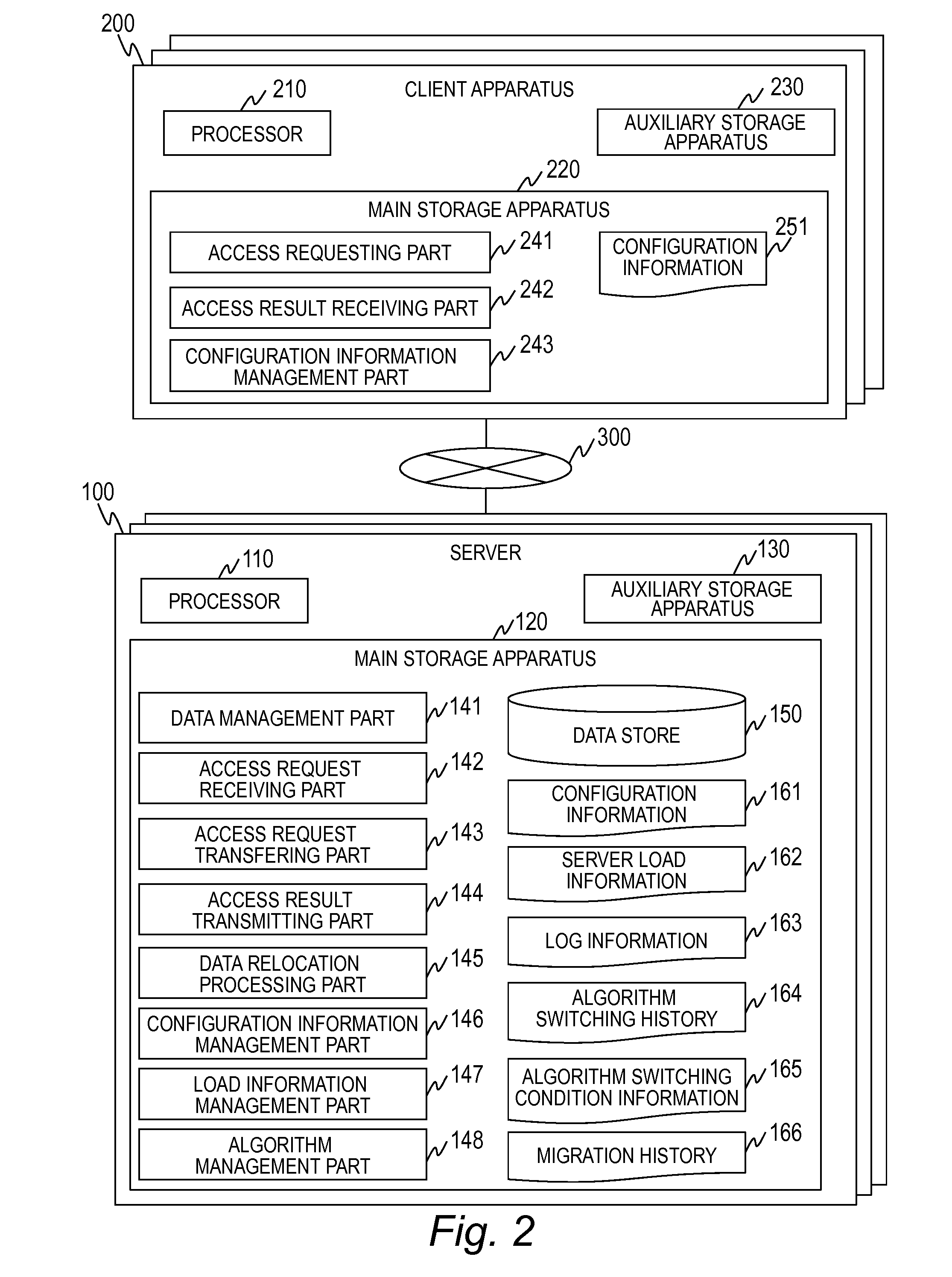
[0061]FIG. 2 is a block diagram illustrating a configuration of a computer system according to a first embodiment of the present invention.
[0062]A computer system includes a plurality of servers 100, a plurality of client apparatuses 200, and a network 300. The respective servers 100 or the server 100 and the client apparatus 200 are connected to each other by the network 300.
[0063]The network 300 may employ various cable and wireless configurations such as a LAN, a WAN, or a SAN. In the present invention, the network 300 may be any network if the network enables the server 100 and the client apparatus 200 to communicate with each other. The network 300 includes a plurality of network apparatuses (not illustrated). The network apparatus includes a switch, a gateway, or the like, for example.
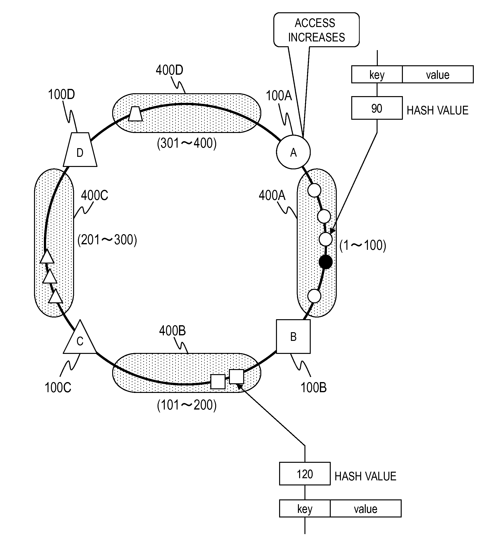
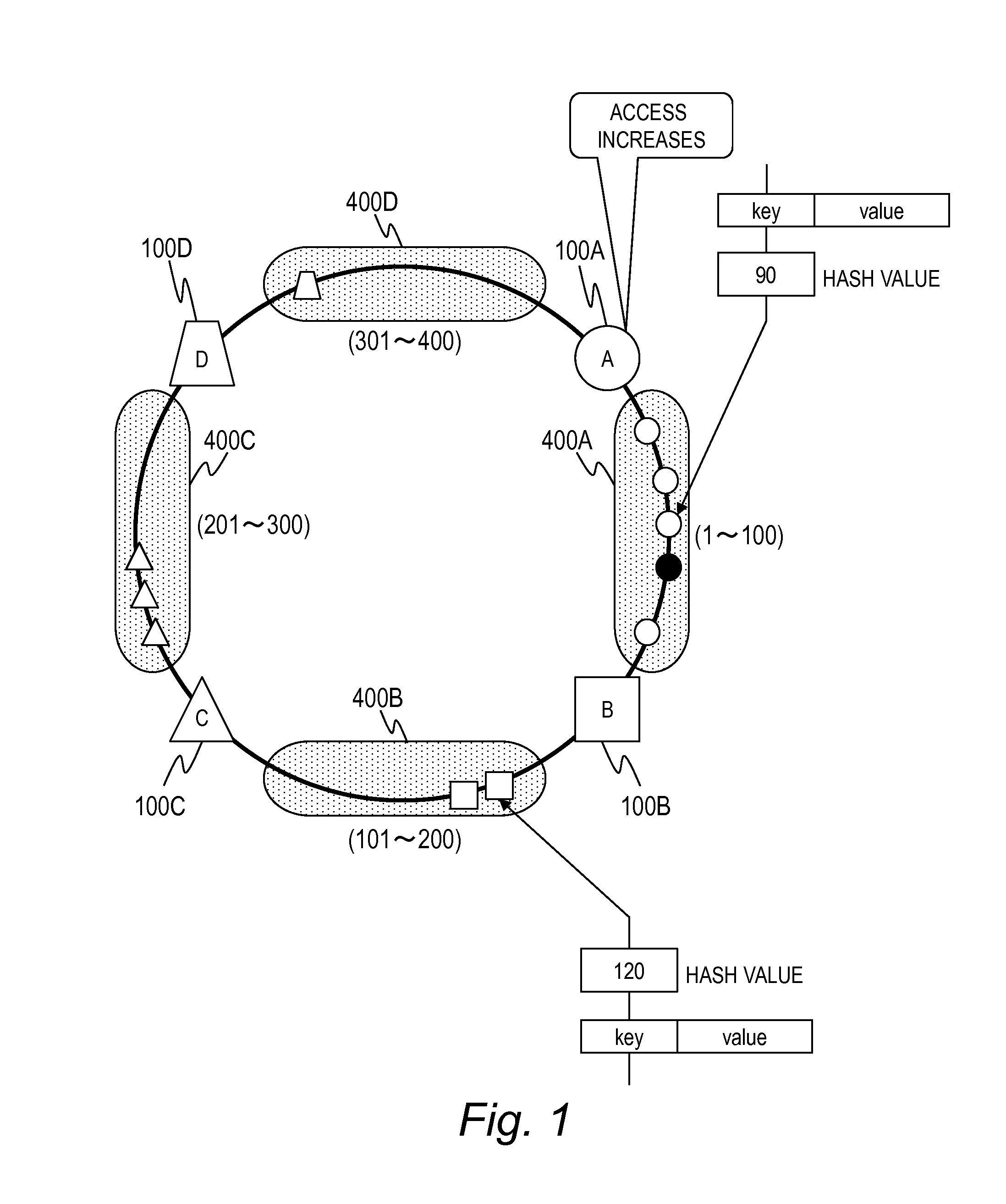
[0064]In the present embodiment, a plurality of servers 100 forms a cluster, and a NoSQL database is constructed on the storage area included in each of these servers 100. In the present embodime...
second embodiment
[0202]FIG. 21 is a block diagram illustrating the configuration of a computer system according to a second embodiment of the present invention. The second embodiment is different from the first embodiment in that the client apparatus 200 does not include the configuration information management part 243 and the configuration information 251.
[0203]Thus, the access request issuing process of the second embodiment is different from that of the first embodiment. Specifically, the process of step S502 is omitted, because the client apparatus 200 does not include the configuration information 251. In this case, the client apparatus 200 transmits an access request to any server 100 coupled to the network 300.
[0204]The server 100 received the access request executes the processes illustrated in FIGS. 13 and 16 to transmit the access result.
[0205]The other configuration and process are the same as those of the first embodiment, and description thereof will not be provided.
third embodiment
[0206]The third embodiment is different in that the server 100 holds the slave data of the other server 100. Thus, the content of the configuration information 161 in the third embodiment is different. Moreover, the access process and the relocation process of the third embodiment are different. Hereinafter, the third embodiment will be described focusing on the difference from the first embodiment.
[0207]Since the configuration of the computer system is the same as that of the first embodiment except for the configuration information 161, the description thereof will not be provided.
[0208]FIG. 22 is a diagram illustrating an example of the configuration information 161 in the third embodiment of the present invention.
[0209]In the configuration information 161 of the third embodiment, the information stored in the management range 1612 is different. The management range 1612 includes Master 1615, Slave1 1616, and Slave2 1617 as new management items.
[0210]The Master 1615 stores the va...
PUM
 Abstract
Description
Claims
Application Information
 - R&D
- Intellectual Property
- Life Sciences
- Materials
- Tech Scout
- Unparalleled Data Quality
- Higher Quality Content
- 60% Fewer Hallucinations
Browse by: Latest US Patents, China's latest patents, Technical Efficacy Thesaurus, Application Domain, Technology Topic, Popular Technical Reports.
© 2025 PatSnap. All rights reserved.Legal|Privacy policy|Modern Slavery Act Transparency Statement|Sitemap|About US| Contact US: help@patsnap.com