Battery pack and electrical apparatus
- Summary
- Abstract
- Description
- Claims
- Application Information
AI Technical Summary
Benefits of technology
Problems solved by technology
Method used
Image

Examples
first embodiment
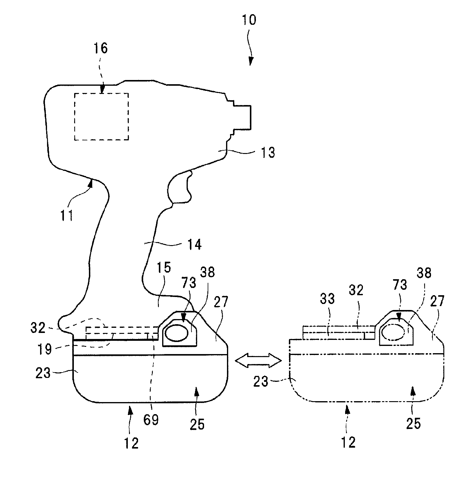
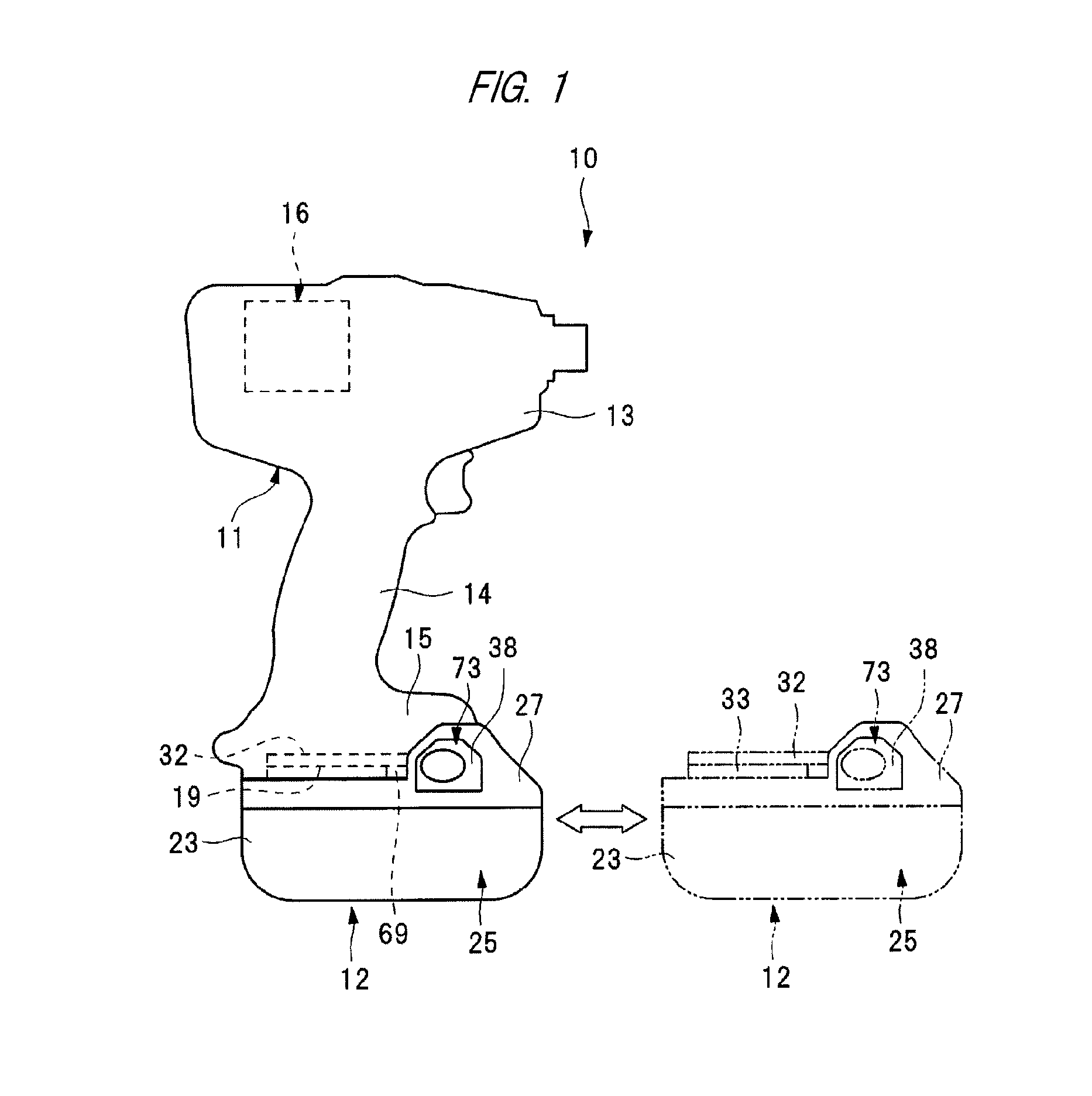
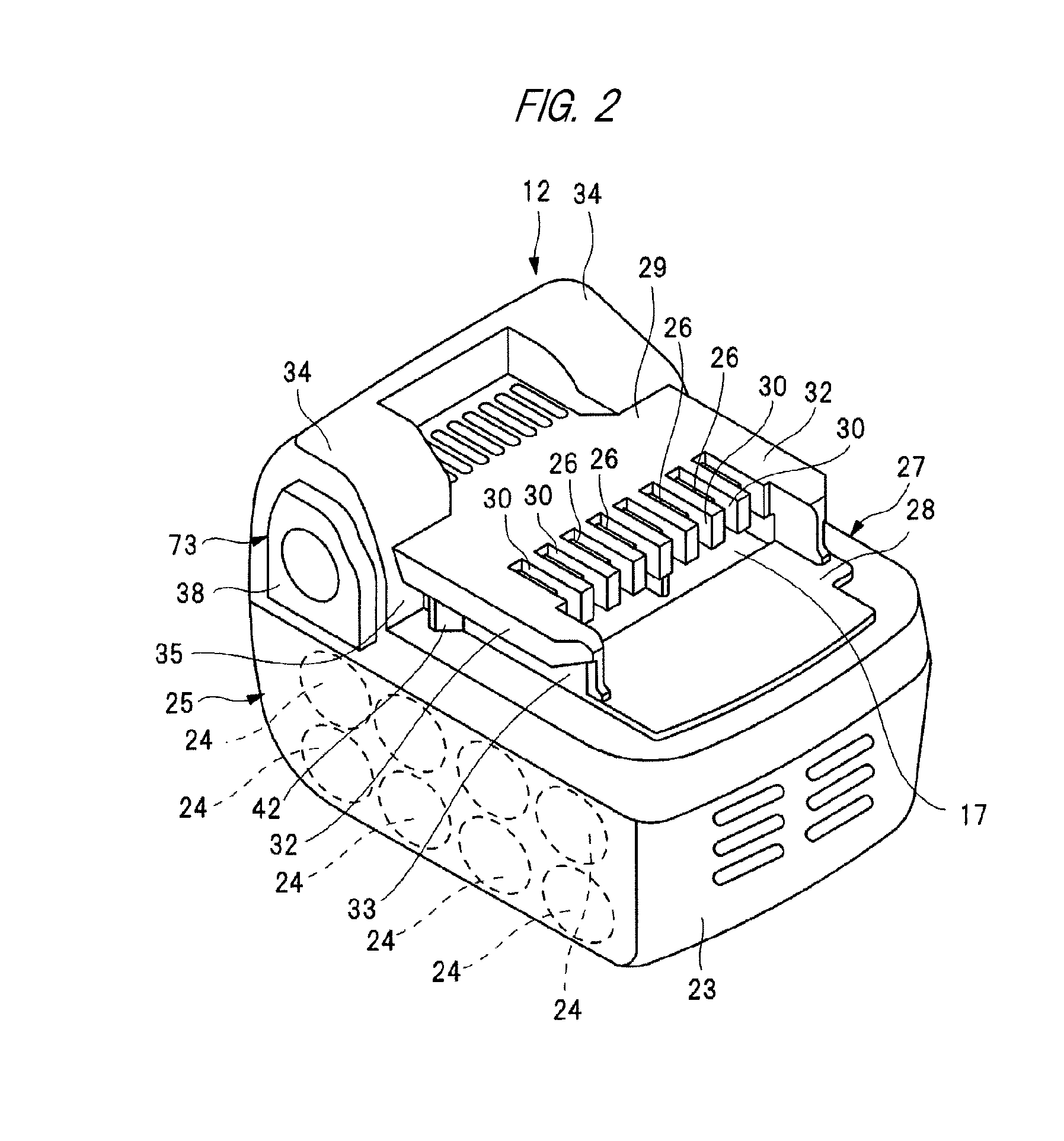
[0043]The cover 27 has a flat plate portion 28 and a mount portion 29 different in height from the plate portion 28. The mount portion 29 has multiple terminal insertion holes 30 formed into slit-like shapes. The terminal insertion holes 30 communicatively connect the inside of the housing case 25 to the outside of the same. Each of the battery-side terminals 26 is inserted in each of the terminal insertion holes 30. An opening 17 is formed between the terminal insertion holes 30 and the plate portion 28. The opening 17 communicates with the terminal insertion holes 30.
[0044]The mount portion 29 is provided with two guide rails 32. The guide rails 32 are elements that come in contact with the guide rails 19 to regulate the direction of sliding of the housing case 25. The guide rails 32 are equivalent to a second guide unit of the present invention. The two guide rails 32 are located on both sides of the terminal insertion holes 30, respectively. In a plan view of the battery pack 12...
second embodiment
[0059]A second embodiment of the cover 27 used for the battery pack 12 of FIGS. 1 and 2 will be described, referring to FIG. 6. The same structural parts of the cover 27 of FIG. 6 as structural parts of the cover 27 of FIGS. 4 and 5 are denoted by the same reference numerals used in FIGS. 4 and 5. According to the cover 27 of FIG. 6, on the inner surface of the cover 27, a rib 49 is formed between the rib 43 and the terminal insertion holes 30. The rib 49 is parallel with the ribs 43.
[0060]A rib 50 is provided to the operation part 38 such that the rib 50 is located between the ribs 43 and the rib 49 in the longitudinal direction of the guide groove 33. An elastic member 51 serving as an energizing member is interposed between the rib 49 and the rib 50. The elastic member 51 is fixed to either the rib 49 or the rib 50, and is molded integrally with rubber, etc. When the latch mechanism 73 is being attached to the cover 27, the elastic member 51 is compressed and elastically deformed...
third embodiment
[0066]A third embodiment of the cover 27 used for the battery pack 12 of FIGS. 1 and 2 will be described, referring to FIG. 10. The same structural parts of the cover 27 of FIG. 10 as structural parts of the cover 27 of FIGS. 4 and 5 are denoted by the same reference numerals used in FIGS. 4 and 5. According to the cover 27 of FIG. 10, an elastic member 52 serving as an energizing member is interposed between one of two ribs 43 that is located on the far side to the guide groove 33 and the inner surface of the concave portion 40. The elastic member 52 is fixed to either the rib 43 or the inner surface of the concave portion 40, and is molded integrally with rubber, etc.
[0067]When the latch mechanism 73 is in its state of attachment to the cover 27, the elastic member 52 is compressed and elastically deformed by the rib 43 and the inner surface of the concave portion 40. As a result, in a bottom view of the cover 27, the elastic member 52 pushes the latch mechanism 73 along the longi...
PUM
 Abstract
Description
Claims
Application Information
 - R&D
- Intellectual Property
- Life Sciences
- Materials
- Tech Scout
- Unparalleled Data Quality
- Higher Quality Content
- 60% Fewer Hallucinations
Browse by: Latest US Patents, China's latest patents, Technical Efficacy Thesaurus, Application Domain, Technology Topic, Popular Technical Reports.
© 2025 PatSnap. All rights reserved.Legal|Privacy policy|Modern Slavery Act Transparency Statement|Sitemap|About US| Contact US: help@patsnap.com