
Hole Plug

a technology of flexing portion and hole, which is applied in the field of hole plugs, can solve the problems of partially interfering annular outer edge of the brim-like flexing portion, and achieve the effect of length dimension and shortening the distance between the bent portion

Active Publication Date: 2014-10-23
DAIWA KASEI IND CO LTD
View PDF32 Cites 7 Cited by
  • Summary
  • Abstract
  • Description
  • Claims
  • Application Information

AI Technical Summary

Benefits of technology

The invention is a brim-like flexing portion that is used to securely install a hole plug in an installation hole. The brim-like flexing portion flexes around the installation hole and sandswiches the outer peripheral portion together with an elastic pawl portion. The length of the brim-like flexing portion is determined by the diameter of the flexing base portion and the hole diameter of the installation hole. The brim-like flexing portion is designed to have a suitable abutment intimate contacting force with the outer peripheral surface around the installation hole. The reduced-diameter portion on the fit side wall portion prevents interference with the round corner parts of the bent portions, which enables the hole plug to be securely installed. The brim-like flexing portion is designed to have flexibility to suppress a reaction force applied to the hole plug from the installed member, which reduces the inserting load required for the hole plug.

Problems solved by technology

In such a case, with the hole plug installed to the installed member in the installation hole, the annular outer edge of the brim-like flexing portion may partially interfere with a round corner part of the bent portion.

Method used


Image

  • Hole Plug
  • Hole Plug
  • Hole Plug

Examples


Embodiment Construction

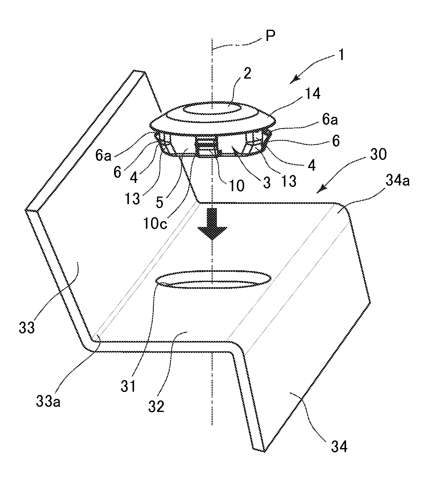
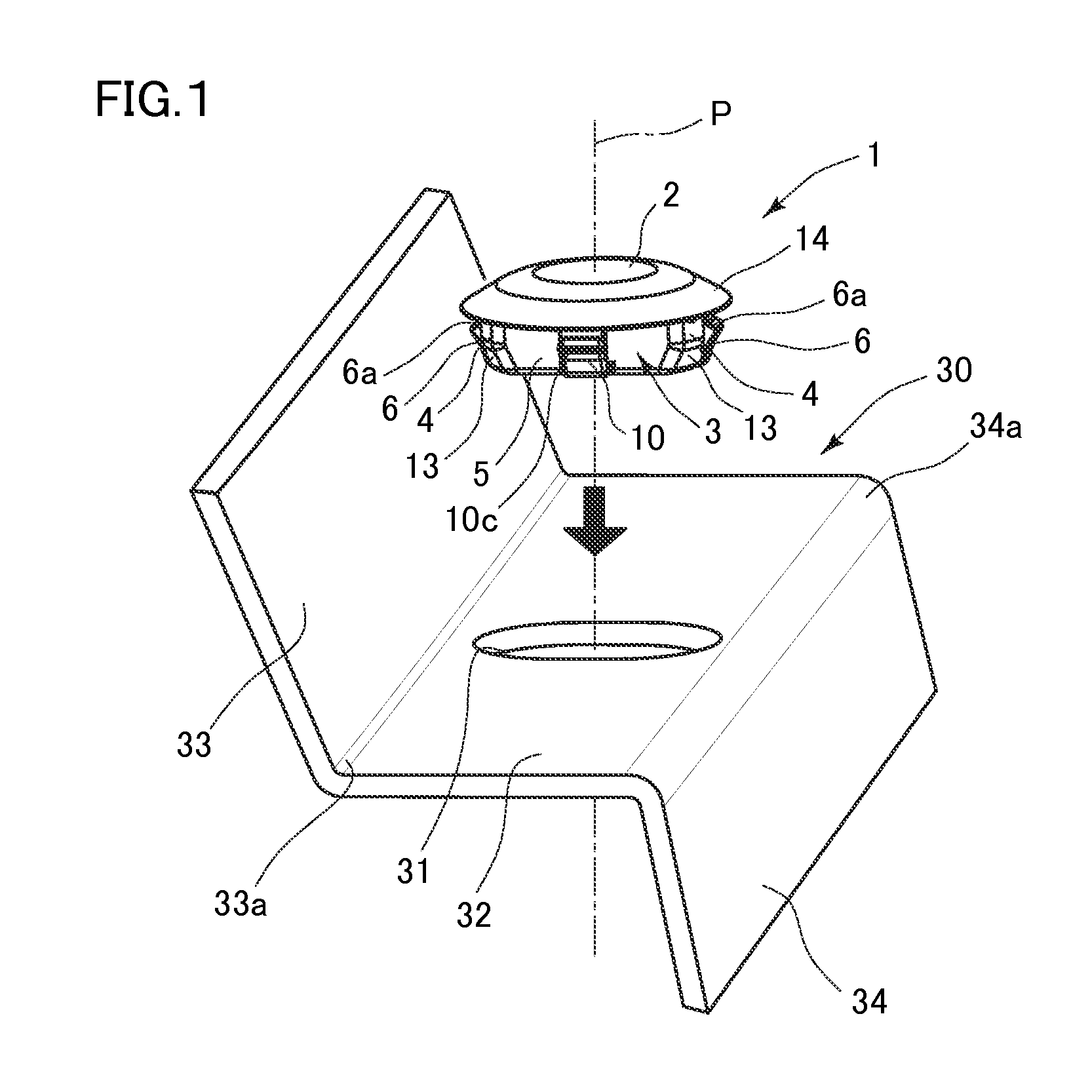
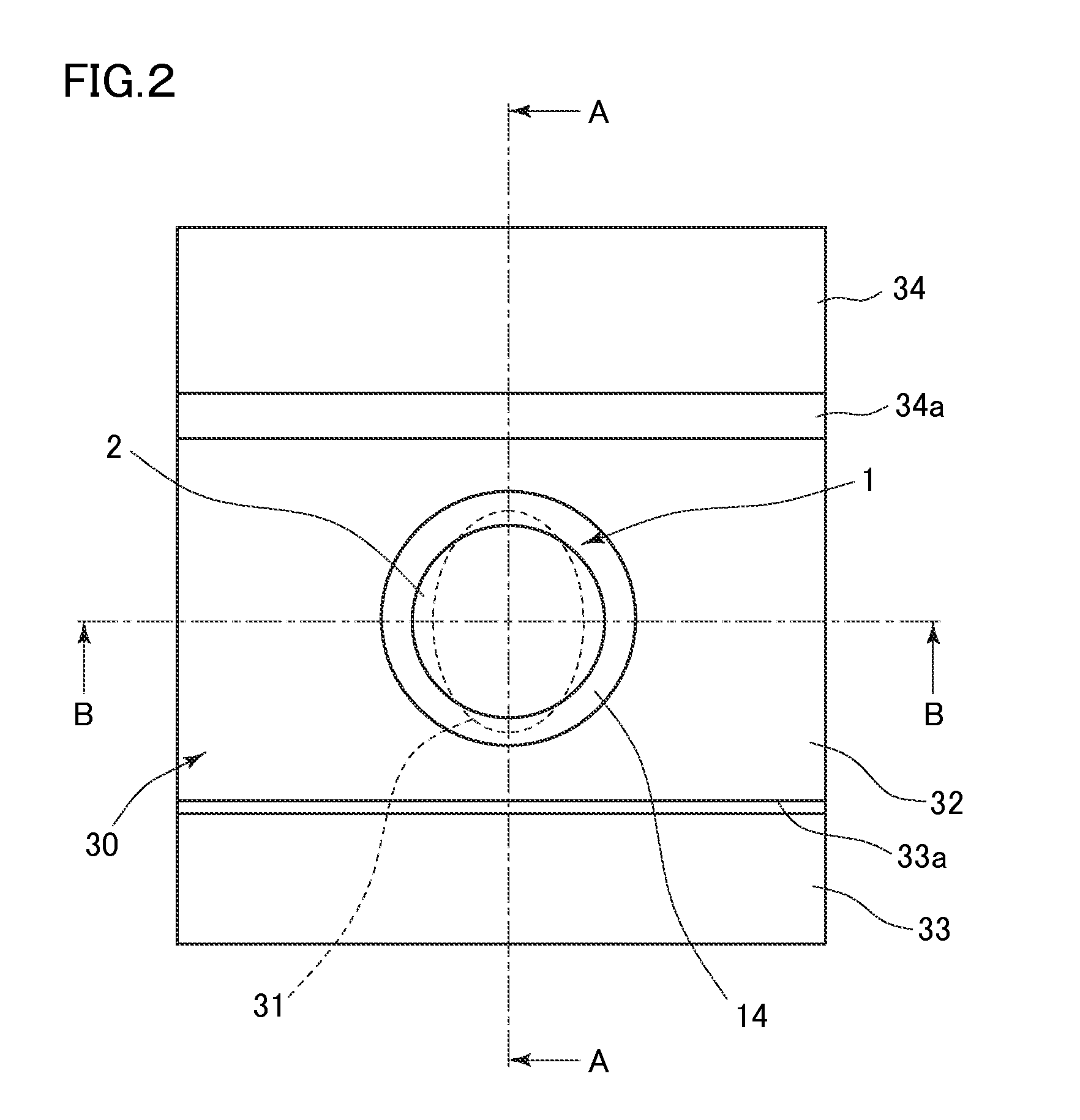
[0022]In the following, one embodiment of the invention will be explained with reference to attached drawings. As shown in FIGS. 1 and 2, a hole plug 1 is installed to a body panel 30 as an installed member in or at an installation or insertion hole 31. The body panel 30 is made from a plate-like member by bending, and it is formed of an installation hole 31 by perforating. In this embodiment, the installation hole 31 is formed as an elliptic hole. The body panel 30 constitutes for example an outer plate of an automobile. The installation hole 31 perforated on the outer plate is used as a working hole, and becomes unnecessary when the automobile is operated after the assembling work has been completed. For this reason, the hole plug 1 is installed to or inserted into the installation hole 31 of the body panel 30 to block it. Here, the hole plug 1 has a water-proof function which prevents a flow of water in both directions between an outside and an inside of the body panel 30 for blo...


PUM


Abstract

A brim-like flexing portion flexes via an abutment to an outer peripheral surface around an installation hole of an installed member, and it sandwiches an outer peripheral portion around the installation hole together with the elastic pawl portion. In determining a set dimension of the brim-like flexing portion, a diameter dimension of a flexing base portion is set in a value between an outer diameter dimension of a reduced-diameter portion and a hole diameter dimension of the installation hole.

Description

RELATED APPLICATIONS[0001]This application claims the priority of Japanese Patent Application No. 2013-089112 filed on Apr. 22, 2013. The disclosure of the prior application is hereby incorporated herein in the entirety by reference.BACKGROUND OF THE INVENTION[0002]1. Field of the Invention[0003]The invention relates to a hole plug installed to an installed member having an installation hole by insertion to block the installation hole with its blocking surface portion.[0004]2. Description of Related Art[0005]Conventionally, an installed member such as a body panel of a vehicle (an automobile) etc. is formed of installation holes such as plug holes etc. The installation holes are used during assembling of the vehicle for various working. Some of the plug holes not used during operation etc. of the vehicle may be left unblocked, and allow foreign matters such as water, mud etc. to enter into a compartment therethrough. To prevent such entry of the foreign matters, a hole plug which bl...

Claims


Application Information

Patent Timeline
Patent Type & Authority Applications(United States)
IPC IPC(8): B60R13/07
CPCB60R13/07B62D25/24
Inventor IWAHARA, TOSHIOKATO, MAKOTOKATAOKA, HIROFUMIOGINO, TETSUYA
Owner DAIWA KASEI IND CO LTD
Learn More