
Electronic drive circuit for a MEMS type resonator device and method for actuating the same

a technology of resonator device and electronic drive circuit, which is applied in the direction of acceleration measurement using interia force, speed measurement using gyroscopic effects, devices using electric/magnetic means, etc., can solve the problems of system power consumption, electrical power consumption of the system, and the start time of the gyroscope drive circuit to be reduced, so as to reduce the start time and reduce the electrical power consumption

Active Publication Date: 2014-10-16
EM MICROELECTRONIC-MARIN
View PDF1 Cites 5 Cited by
  • Summary
  • Abstract
  • Description
  • Claims
  • Application Information

AI Technical Summary

Benefits of technology

The invention provides an electronic drive circuit for a MEMS type resonator device that minimizes power consumption and reduces the time needed to start the device. The circuit maximizes the energy transmitted to the resonator while avoiding the need for a high supply voltage. The circuit is also less complex than existing circuits that perform the same functions. The starting time of the electronic circuit for setting the resonator in oscillation is greatly reduced, allowing for the use of a simple RC oscillator. This electronic drive circuit can be integrated into a reduced surface and simplifies the excitation diagram of the device.

Problems solved by technology

The use of a phase lock loop for maintaining the oscillation of the resonator mass does not reduce the general power consumption of the system for controlling the oscillation phase and amplitude, which is a drawback.
Account must also be taken of a relatively high supply voltage for maintaining the oscillation of said mass, which does not allow the start time of the gyroscope drive circuit to be reduced, which are further drawbacks.
This does not reduce the electrical power consumption of the system, which is a drawback.
Several disruptions are also noted between actuation of the mass oscillation and detection of the mass motion for regulating the oscillation amplitude, which is another drawback.
One drawback of this system is that it uses a VCO oscillator.
This makes it impossible to reduce the general electrical power consumption of the system for controlling oscillation phase and amplitude.
This complicates manufacture, and also the precision of the oscillation phase and amplitude control.
The primary is dependent on the secondary, which is another drawback.

Method used


Image

  • Electronic drive circuit for a MEMS type resonator device and method for actuating the same
  • Electronic drive circuit for a MEMS type resonator device and method for actuating the same
  • Electronic drive circuit for a MEMS type resonator device and method for actuating the same

Examples


Embodiment Construction

[0025]In the following description, all those electronic elements of the electronic drive circuit directly connected to the resonator of the resonator device, which are well known to those skilled in the art in this technical field, will be described only in a simplified manner. Preferably, the resonator device is a gyroscope with a MEMS type sensor or resonator with a high quality factor. The basic functions of the electronic drive circuit are, on the one hand, to oscillate the mass of the primary resonator, i.e. to oscillate the mass in a determined direction, and to control the mechanical oscillation amplitude of the mass.

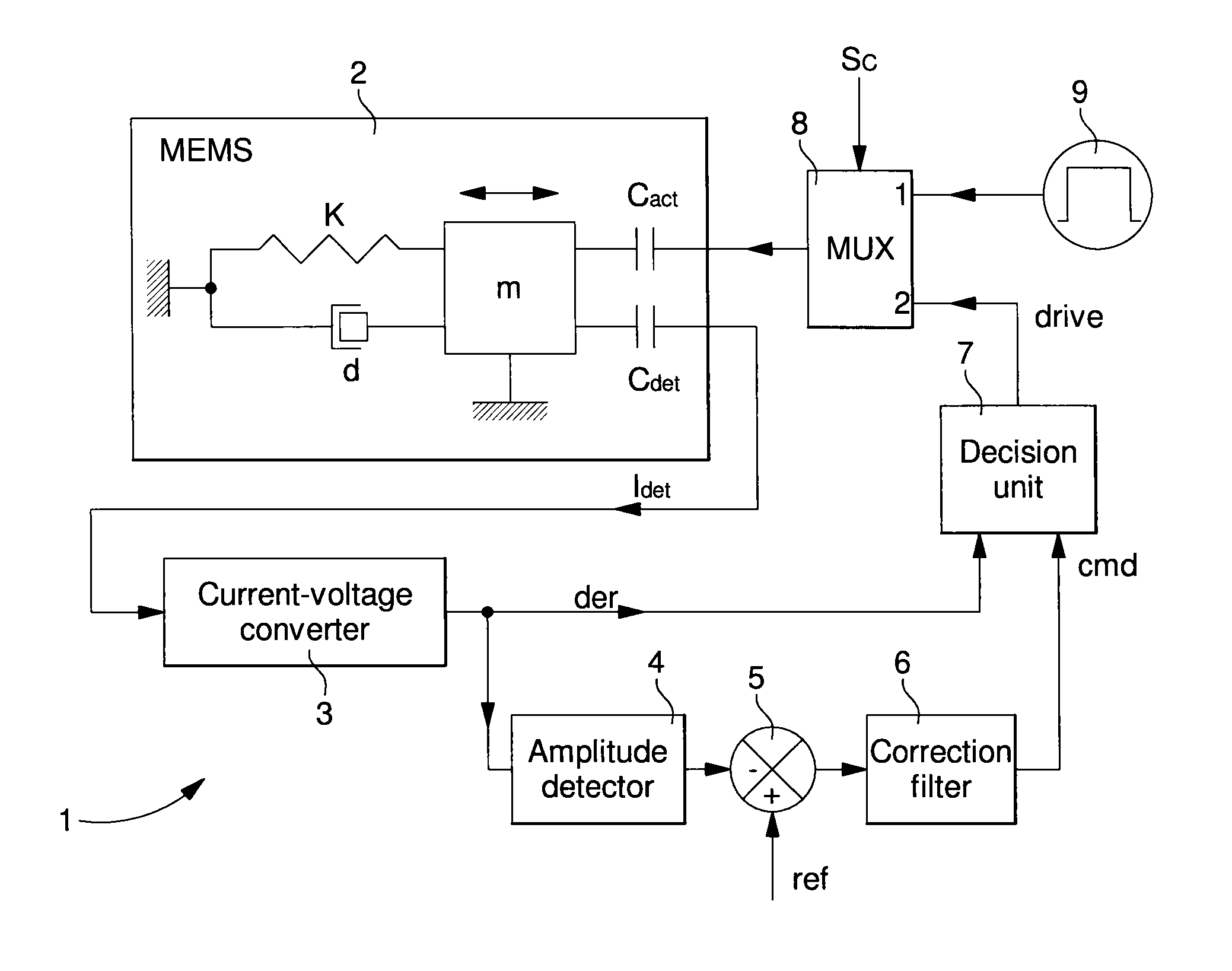
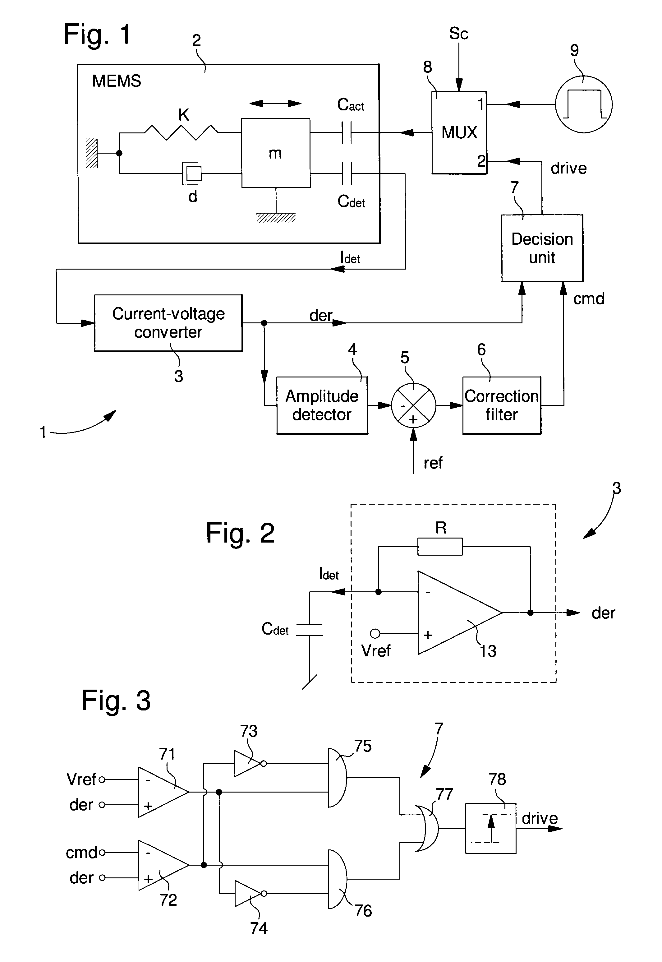
[0026]FIG. 1 shows an embodiment of electronic drive circuit 1 connected to MEMS type resonator 2. Electronic drive circuit 1 on the one hand allows resonator 2 to be actuated via an actuation element Cact and on the other hand allows the motion of a mass m of resonator 2 to be detected via a detection element Cdet. Actuation element Cact and detection element C...


PUM


Abstract

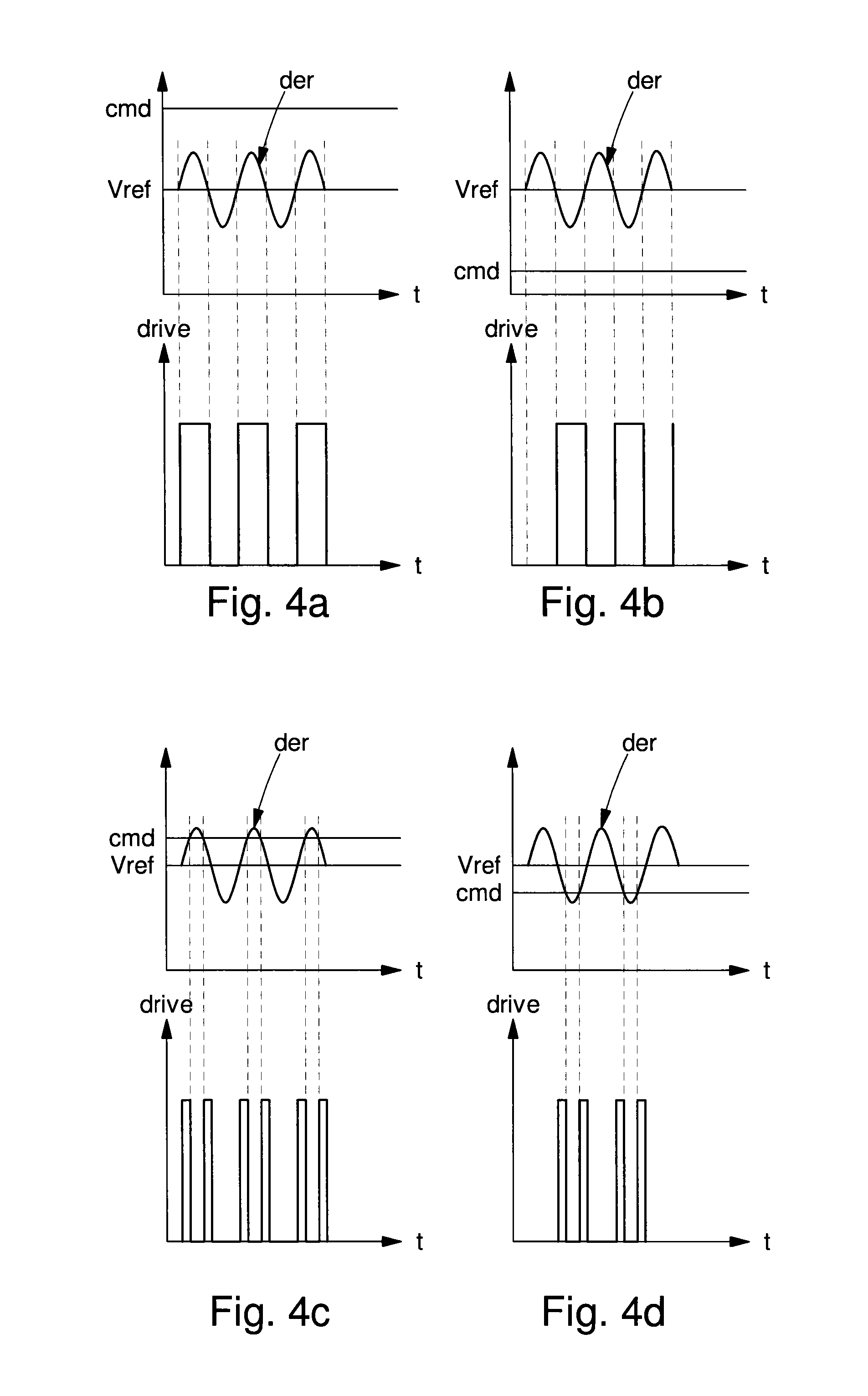
The electronic circuit (1) is for driving a resonator (2) of a MEMS resonator device. The resonator includes a mass (m) connected to a spring (k) and a damping element (d), an actuation element (Cact) for actuating the mass via an actuation signal (drive), and a detection element (Cdet) for detecting motion of the mass. The electronic circuit includes a conversion means (3) connected to the detection element to supply a mass oscillation derivative signal (der), a means (4, 5, 6) of comparing the derivative signal amplitude and a reference amplitude (ref) for supplying a control signal (cmd), and a decision unit (7) for supplying a digital actuation signal (drive). The actuation signal includes rectangular pulses determined on the basis of the derivative signal and of the control signal to adapt the mass oscillation amplitude according to the reference amplitude.

Description

[0001]This application claims priority from European Patent Application No. 13163181.4 filed Apr. 10, 2013, the entire disclosure of which is incorporated herein by reference.FIELD OF THE INVENTION[0002]The present invention concerns an electronic drive circuit for a MEMS type resonator device, and in particular for a MEMS type gyroscope with a high quality factor.[0003]The present invention also concerns the method for actuating the electronic drive circuit for the MEMS type resonator device.BACKGROUND OF THE INVENTION[0004]Conventionally, an electronic circuit connected to a resonator of a MEMS type resonator device can also be used to perform an angular velocity measurement. An angular velocity may be measured on one, two or three axes, for example with a MEMS type gyroscope. The gyroscope generally includes at least one mass maintained by a structure in the form of a spring and capable of being set in oscillation electrically at a frequency determined by the spring constant with...

Claims


Application Information

Patent Timeline
Patent Type & Authority Applications(United States)
IPC IPC(8): G01C19/5712
CPCG01C19/5712G01C19/5776H03B5/30
Inventor ENTRINGER, CHRISTOPHEDESCHILDRE, ALEXANDRE
Owner EM MICROELECTRONIC-MARIN
Learn More