
Air dehumidification unit and process

a technology of air dehumidification unit and air filter, which is applied in the direction of defrosting, heating types, domestic cooling apparatus, etc., can solve the problems of unfavorable dehumidification of heat pump system, unfavorable recirculation of hvac system of vehicle, and undesired fogging of window glass, so as to reduce the consumption of electric power

Inactive Publication Date: 2013-03-28
HANON SYST
View PDF11 Cites 6 Cited by
  • Summary
  • Abstract
  • Description
  • Claims
  • Application Information

AI Technical Summary

Benefits of technology

The patent describes a method for reducing humidity in air by using a heating device. This method involves using an air dehumidification unit with an evaporator and a drainage channel, where humidity in the air is removed and then heated up by the heating device. The heating device can be used indirectly to minimize power consumption and prevent freezing in the drainage pipe. The technical effect of this method is to provide a more efficient and effective way to reduce humidity in air, which can improve various aspects of air dehumidification such as energy efficiency and stability.

Problems solved by technology

One such problem is that, oftentimes, the heat pump systems cannot dehumidify and heat the air to be supplied to a passenger compartment of the vehicle at the same time.
As such, the HVAC system of the vehicle cannot be operated using recirculated air from the passenger compartment.
Due to a lack of the dehumidification of the air, an undesired fogging of window glass occurs.
The resulting water condensate must be removed from the HVAC system at all temperature conditions, particularly at temperatures below 0° C. Hereby, however, the water condensate in a water drainage channel provided to remove the water condensate may freeze, obstructing an outflow of the water condensate.
Moreover, the heating device only covers part of the inner wall of the hose so that the inner wall is not homogeneously heated.

Method used


Image

  • Air dehumidification unit and process
  • Air dehumidification unit and process

Examples


Embodiment Construction

[0031]The following detailed description and appended drawings describe and illustrate various embodiments of the invention. The description and drawings serve to enable one skilled in the art to make and use the invention, and are not intended to limit the scope of the invention in any manner.

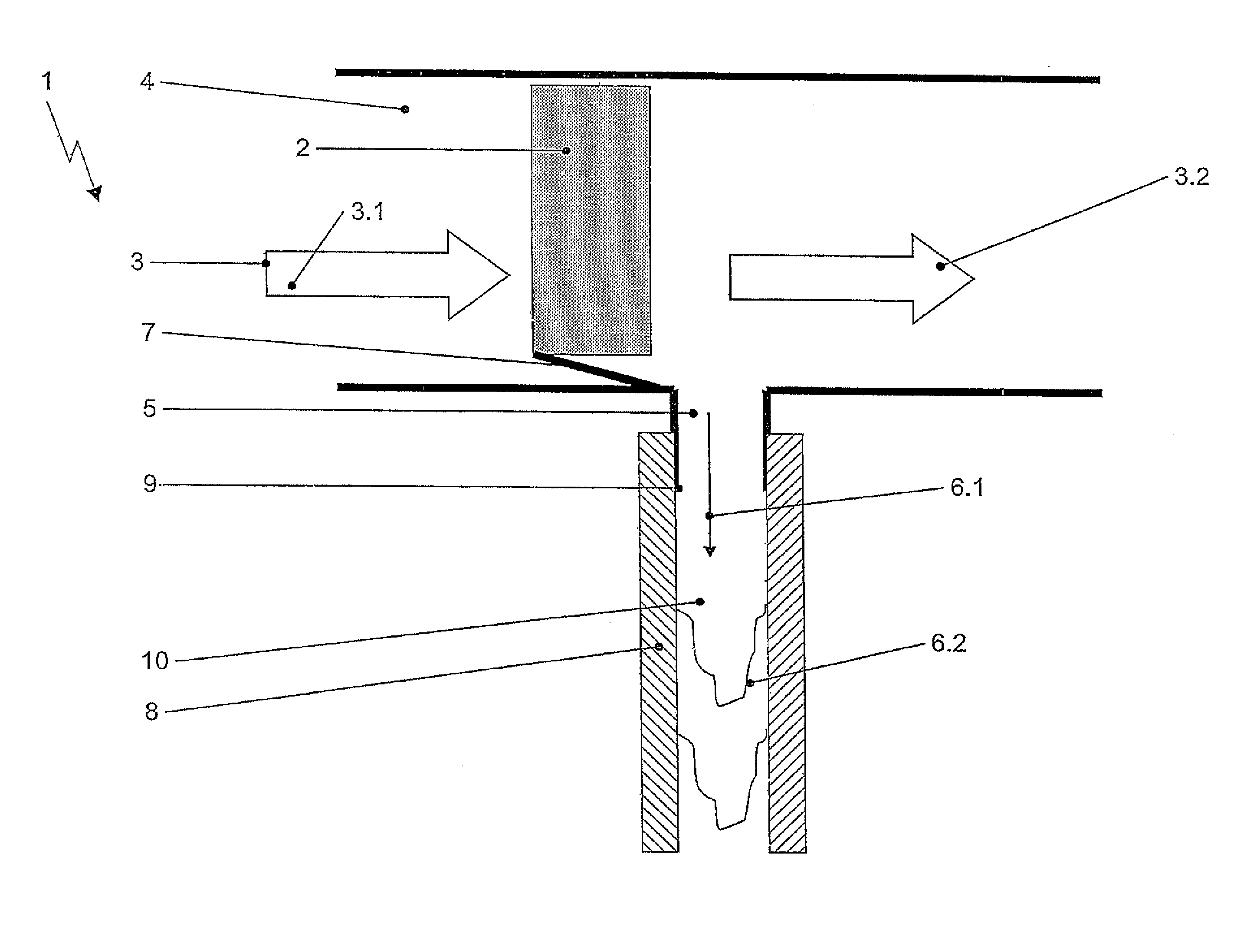
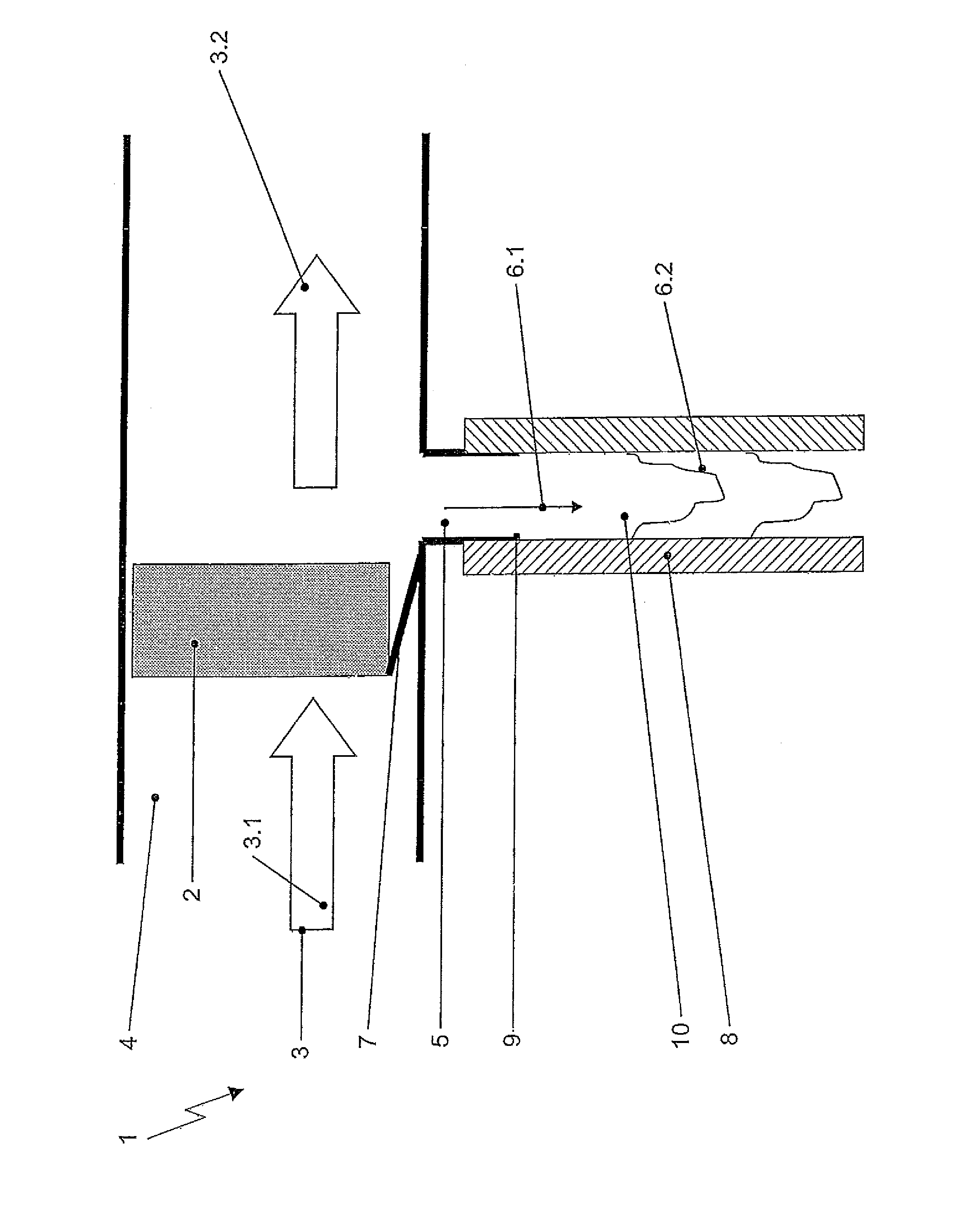
[0032]The drawing shows a section of an HVAC system of a motor vehicle with an air dehumidification unit 1 in a region of an evaporator 2, which serves to supply heat from air to be conditioned 3.1 of an interior of the vehicle to a refrigerant of a heat pump system. The evaporator 2 is located in an air flow channel 4 such that inflowing fresh air 3.1 or recirculating air 3.1 must pass through the evaporator 2. The air to be conditioned 3.1 passes through the evaporator 2 at a temperature of 15° C. and a relative air humidity of 80%, for example. After having passed through the evaporator 2, the dehumidified air has a relative air humidity of 97% and a temperature of 3° C., for example. In a ...


PUM


Abstract

An air dehumidification unit of a heating, ventilating, and air conditioning system includes an air flow channel configured to guide a flow of air through an evaporator disposed therein, and a drainage channel coupled to the air flow channel. The drainage channel has an internal volume configured to receive a fluid condensed at the evaporator from the flow of air. The air dehumidification unit further includes a heating device configured to heat the internal volume of the drainage channel from outside of the internal volume of the drainage channel to militate against a formation of ice therein. The invention also relates to a method for dehumidifying the air in the heating, ventilating, and air conditioning system of a motor vehicle using the air dehumidification unit.

Description

CROSS-REFERENCE TO RELATED APPLICATION[0001]This application claims the benefit of German Patent Application No. DE 10 2011 053 906.9 filed Sep. 23, 2011, the entire disclosure of which is hereby incorporated herein by reference.FIELD OF THE INVENTION[0002]The invention relates to an air dehumidification unit for an HVAC system of a motor vehicle and, more particularly to an air dehumidification unit for an HVAC system of a motor vehicle which is capable of combined refrigeration system and heat pump operation. Further, the invention relates to a process for dehumidifying air to be conditioned of a passenger compartment in the HVAC system operated as a heat pump using the air dehumidification unit.BACKGROUND OF THE INVENTION[0003]Typically, a heating, ventilating, and air conditioning (HVAC) system is used at ambient temperatures above 0° C. In hybrid and electric vehicles efficient heating is necessary. As such, heat pump systems have been developed. For efficiency, refrigerant cir...

Claims


Application Information

Patent Timeline
Patent Type & Authority Applications(United States)
IPC IPC(8): F25D21/14F25D17/06
CPCB60H1/3233F24F2013/227F24F2003/1446F24F3/1405
Inventor GRAAF, MARCHAAS, TOBIASFOCK, UDO
Owner HANON SYST
Learn More