
Multiband antenna and mobile terminal

a multi-band antenna and mobile terminal technology, applied in the direction of simultaneous aerial operations, antenna details, antennas, etc., can solve the problems of increasing the size of the antenna, generating four or more, and the wide band of 704 mhz to 2170 mhz, so as to reduce the cost of the mobile terminal mounted with the multi-band antenna, increase the antenna size and the number of antennas, and reduce the size of the devi

Inactive Publication Date: 2014-10-02
NEC CASIO MOBILE COMM LTD +1
View PDF0 Cites 14 Cited by
  • Summary
  • Abstract
  • Description
  • Claims
  • Application Information

AI Technical Summary

Benefits of technology

The present invention provides a multiband antenna for mobile devices, which can cover multiple bands without increasing the size of the antenna or the number of antennas. This results in a smaller device size, and the cost of the device is significantly reduced because only three chip parts (three inductors) are needed. This makes it possible to design a more inexpensive device compared to using an antenna that requires an additional element or a complicated configuration.

Problems solved by technology

However, even when such means is used, a broadband antenna capable of covering a wide band of 704 MHz to 2170 MHz, which is a frequency band used for mobile terminals, is impossible to realize.
However, there are problems that the antenna is increased in size due to the mounting of three antenna elements; the antenna cannot cover all the frequency bands used for mobile terminals; and the antenna cannot generate four or more resonances.
Therefore, at present, the arrangement of a plurality of antenna elements is the only means to cover multiple bands, resulting in an increase in the size of mobile terminals.

Method used


Image

  • Multiband antenna and mobile terminal
  • Multiband antenna and mobile terminal
  • Multiband antenna and mobile terminal

Examples


exemplary embodiment

Configuration Example of Exemplary Embodiment

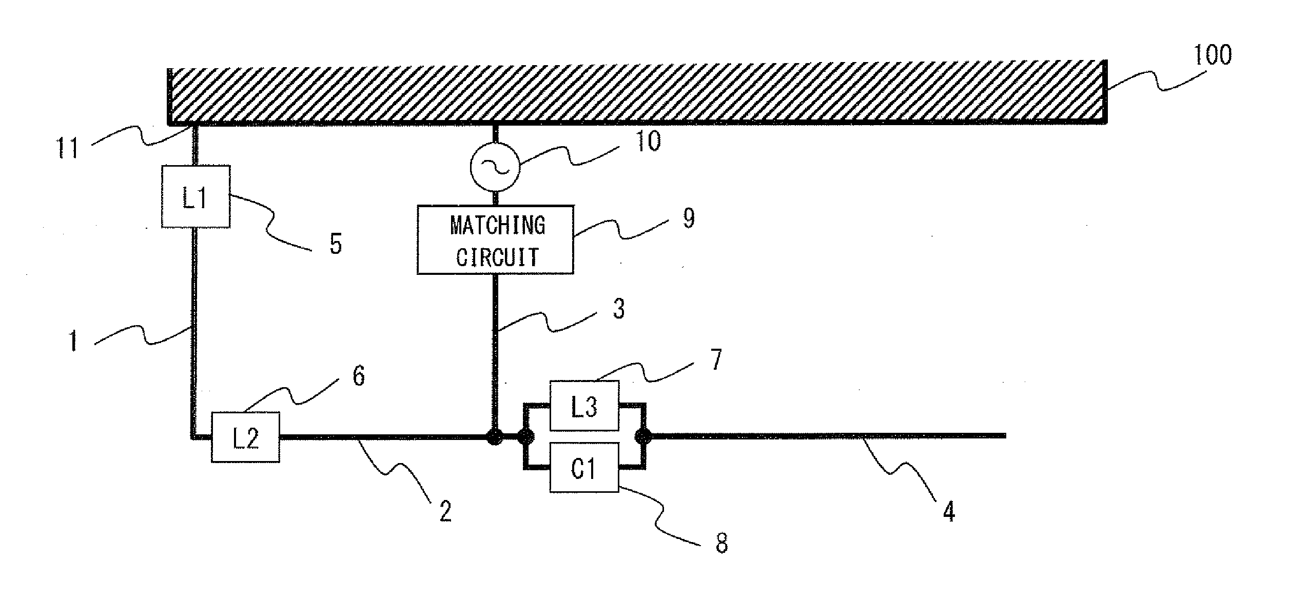
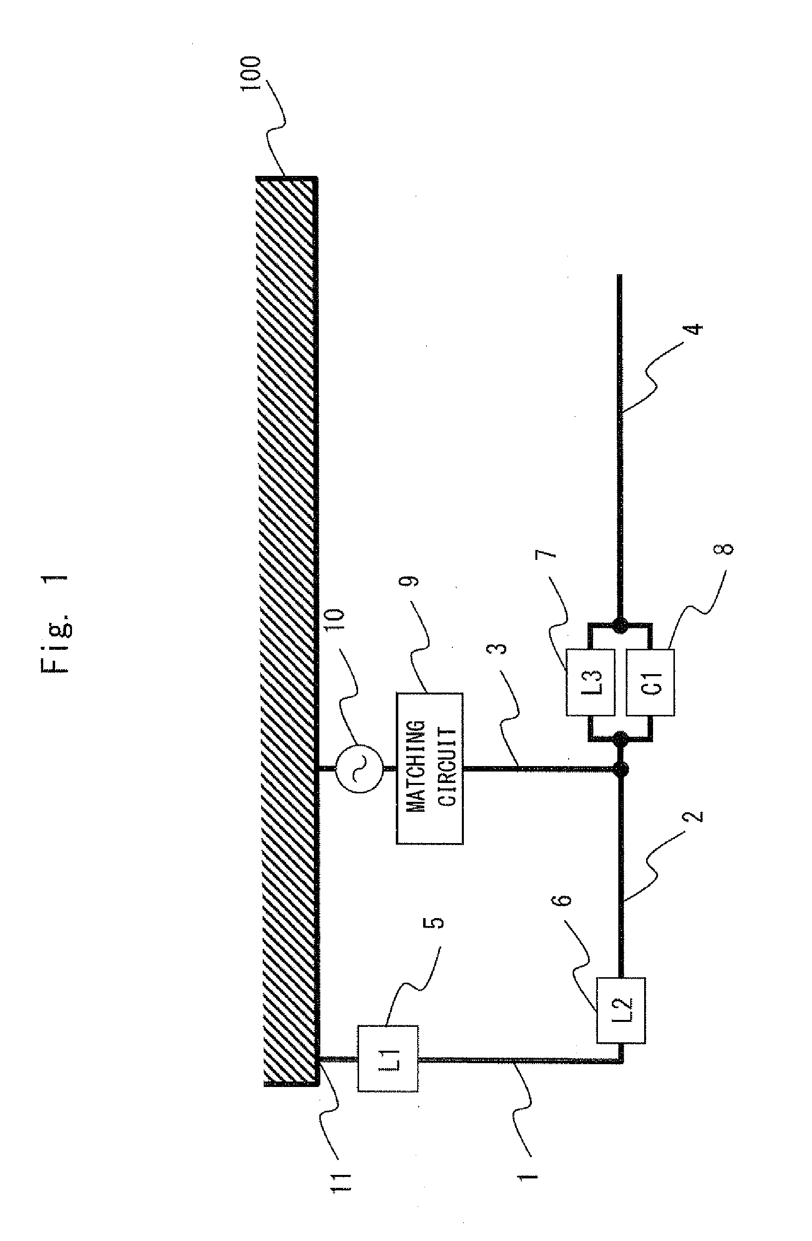
[0074]Next, an example of the circuit configuration of the multiband antenna according to the present invention will be described in detail with reference to FIG. 1. FIG. 1 is a circuit diagram showing an example of the circuit configuration of the multiband antenna according to the present invention, and specifically, showing a configuration example of the multiband antenna that covers a plurality of bands, for example, four bands including a 700 MHz band, a 800 MHz band, a 1.5 GHz band, and a 2 GHz band.

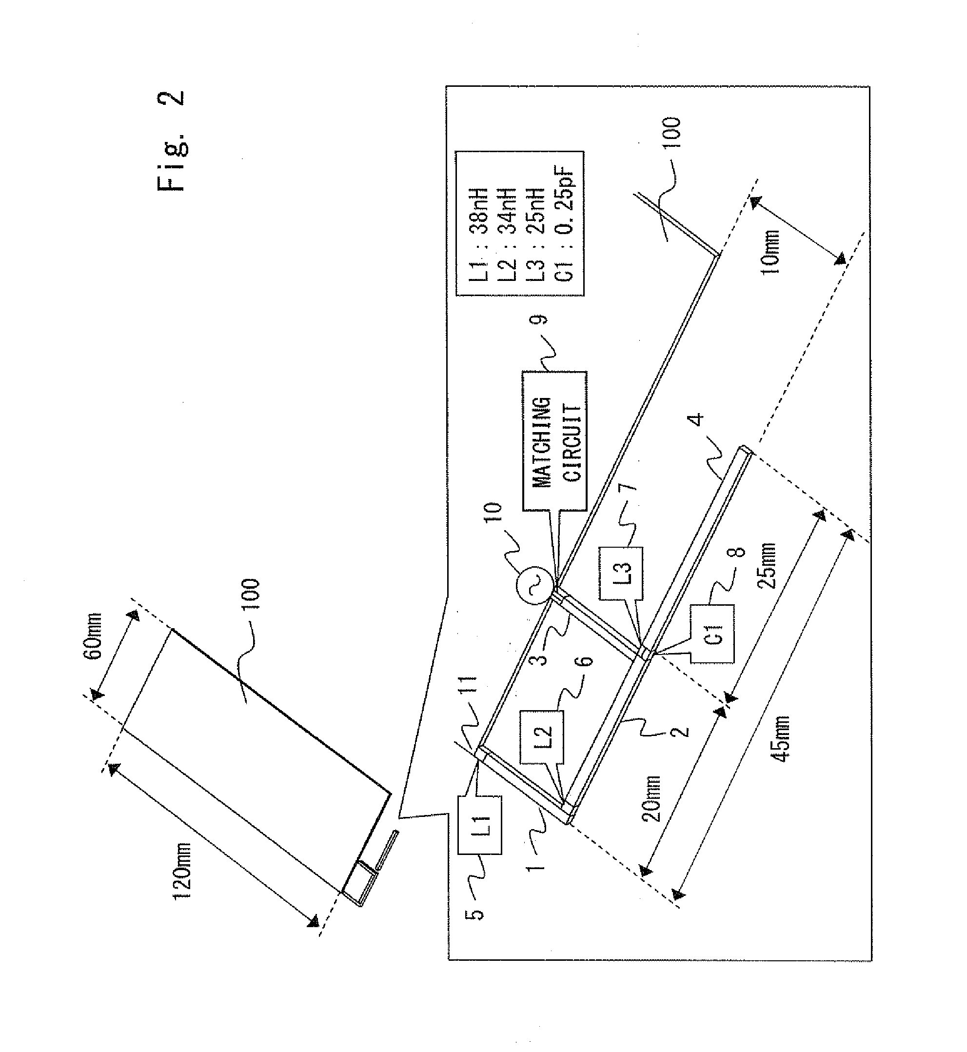
[0075]The multiband antenna shown in FIG. 1 has a configuration in which three inductors, i.e., first to third inductors 5 to 7 having values of inductances L1 to L3, respectively, are additionally provided and arranged in an inverted F-shaped antenna formed of four miniaturized antenna elements, i.e., first to fourth antenna elements 1 to 4. Referring to FIG. 1, a capacitor 8 having the value of a capacitance C1 is connected in parallel...


PUM


Abstract

The antenna has a configuration in which three inductors, i.e., first to third inductors 5 to 7 having values of inductances L1 to L3, respectively, are arranged in an inverted F-shaped antenna formed of miniaturized four antenna elements, i.e., first to fourth antenna elements 1 to 4 with an element length shorter than that of each wavelength of desired resonance frequencies are grounded at a GND ground point 11. A power feeding unit 10 feeds electric power to the inverted F-shaped antenna through a matching circuit 9, thereby enabling a plurality of antenna operations of a two-resonance loop antenna that resonates at two resonance frequencies on a high-frequency side, an inverted F-shaped antenna that resonates at two resonance frequencies on a low-frequency side, and an inverted L-shaped antenna.

Description

TECHNICAL FIELD[0001]The present invention relates to a multiband antenna and a mobile terminal, and more particularly, to a miniaturized antenna which is mounted in a mobile terminal, such as a mobile phone or a smartphone, and covers multiple bands.BACKGROUND ART[0002]Recently, with the rapid widespread of smartphones as well as mobile phones, the amount of data downloaded through mobile terminals has significantly increased. To deal with the increase of the data traffic, the traffic is distributed to a plurality of frequency bands, or new communication standards, such as LTE (Long Term Evolution), are adopted. Thus, the frequencies to be used have been increasingly diversified.[0003]The frequency bands used differ from country to country. Considering the use of mobile terminals overseas, it is necessary that the mobile terminals cover an extremely large number of frequency bands. As a means to deal with this, a broadband antenna or a multiband antenna can be adopted. As means to ...

Claims


Application Information

Patent Timeline
Patent Type & Authority Applications(United States)
IPC IPC(8): H01Q9/04H01Q5/10
CPCH01Q9/04H01Q1/243H01Q7/005H01Q9/0421H01Q5/321H01Q5/335
Inventor SUZUKI, MASAKIKITANO, SHINICHIRO
Owner NEC CASIO MOBILE COMM LTD
Learn More