E-pdcch mapping, and method and apparatus for transmission and reception in wireless communication system

a wireless communication system and mapping technology, applied in the direction of wireless communication, wireless communication, transmission path sub-channel allocation, etc., can solve the problem that control information may not be quickly utilized, reduce the complexity of blind detection of user equipment, reduce the decoding delay of e-pdcch, and improve the efficiency of transmission of e-pdcch

Inactive Publication Date: 2014-09-25
PANTECH CO LTD
View PDF5 Cites 22 Cited by
  • Summary
  • Abstract
  • Description
  • Claims
  • Application Information

AI Technical Summary

Benefits of technology

[0007]The present specification executes resource mapping in the state in which distributed resource allocation is used, so as to support E-PDCCH transmission appropriately for a channel state of each user equipment, and limits the size of a search space where a user equipment determines the E-PDCCH, so as to reduce complexity of the blind detection of the user equipment. This may reduce decoding delay of the E-PDCCH and thus, the efficiency of transmission of the E-PDCCH may be improved.

Problems solved by technology

However, when the control information is transmitted in the wireless resource as opposed to in a transmission region of the control information, the control information may not be quickly utilized.

Method used


Image

  • E-pdcch mapping, and method and apparatus for transmission and reception in wireless communication system
  • E-pdcch mapping, and method and apparatus for transmission and reception in wireless communication system
  • E-pdcch mapping, and method and apparatus for transmission and reception in wireless communication system

Examples


first embodiment

[0093]According to a detailed example of the first embodiment, an E-PDCCH may have various aggregation levels (aggregation level, AL) in the UE specific region and the common region, and an E-PDCCH aggregation level that each UE may have may be limited so as to reduce the complexity (blind detection complexity) of blind detection executed by the UE. Also, an E-PDCCH region in each UE executes reception may be limited to a common or UE specific region, through a high layer signaling. For example, the UE0 may be limited to receive only an E-PDCCH of AL 4 in only the common region. The limitation may be a UE specific or cell specific limitation, or may limit the entire system. As another example, an eNB may inform each UE of E-PDCCH resource limitation information for each resource.

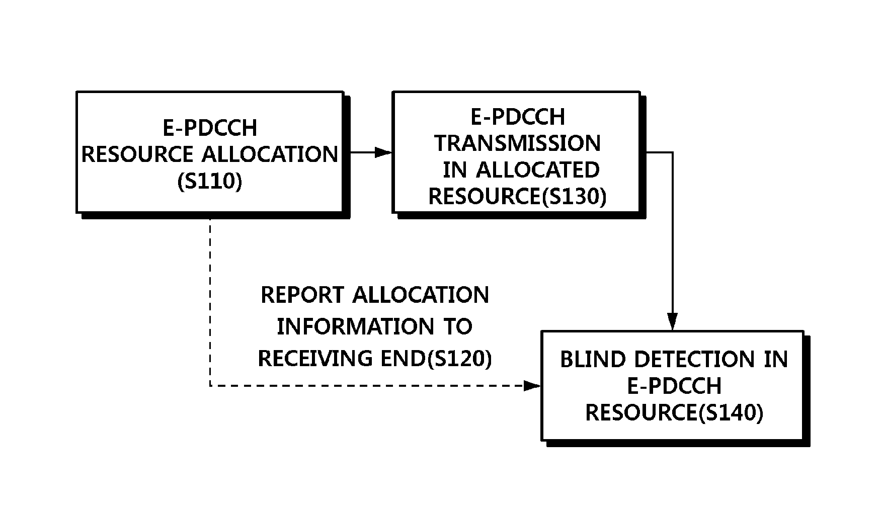
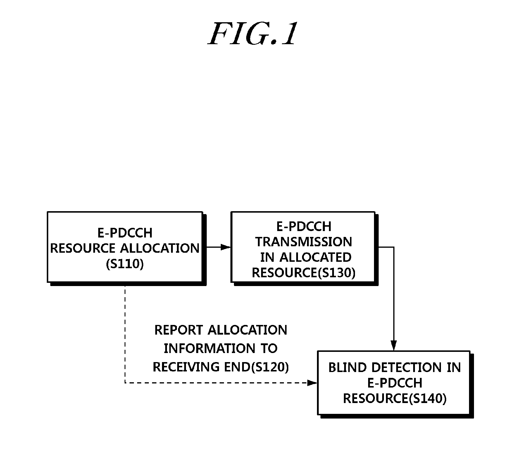
[0094]The signaling scheme will be described in more detail as follows. When each UE desires to receive an E-PDCCH without a separate high layer signaling transferred through a PDSCH, E-PDCCH resource alloca...

second embodiment

[0098]According to the present invention, a blind detection complexity of a user equipment may be reduced by modifying or changing an E-PDCCH mapping scheme based on an aggregation level.

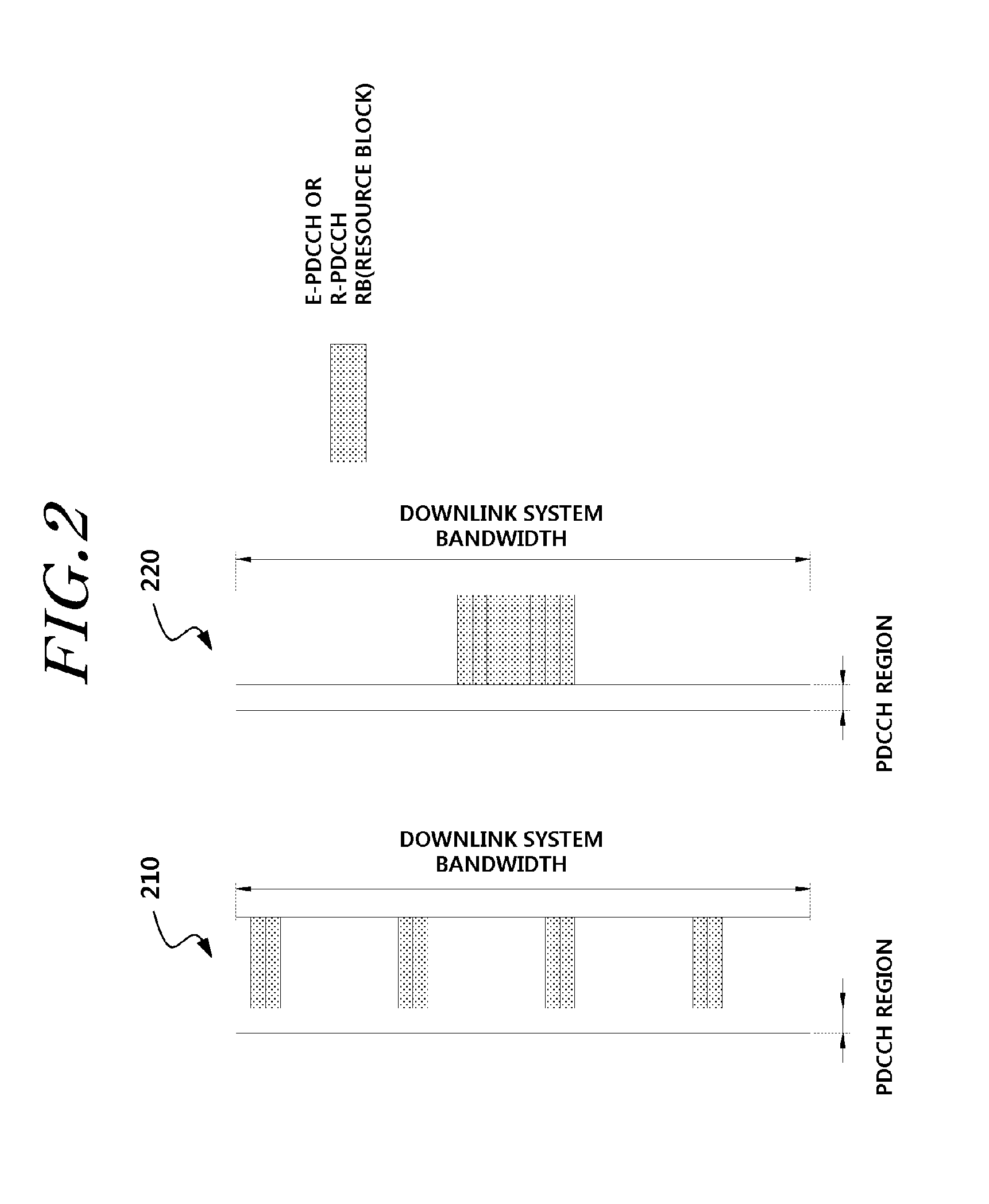
[0099]When the first embodiment of the present invention is applied, an E-PDCCH region allocated to each UE may be divided into a frequency selective scheduling region (UE specific region) and a frequency diversity region (common region) and thus, an E-PDCCH region that provides a scheduling gain may be reduced. This may be a factor that reduces utilization of the E-PDCCH region.

[0100]According to the second embodiment, an E-PDCCH region is set for each UE, and an E-PDCCH transmission scheme is determined in each region, based on an E-PDCCH aggregation level. As described above, in the case in which an E-PDCCH region is set through distributed resource allocation, when an aggregation level becomes high, this may be construed to be a wideband E-PDCCH transmission as opposed to narrow band E-PDCCH tra...


PUM


Abstract

The present invention relates to E-PDCCH (Extended PDCCH) mapping, and a method and an apparatus for transmission and reception in a wireless communication system. The E-PDCCH mapping and the transmission method according to one embodiment of the present description, includes the steps of: enabling a base station to perform distributed resource allocation for two or more regions to which the E-PDCCH is transmitted; and mapping the E-PDCCH to be transmitted to a user terminal by applying a mapping rule to resources of one or more regions among the two or more regions. The mapping rule includes at least one of a first mapping rule for mapping the E-PDCCH to a resource within a pre-indicated region in the terminal, and a second mapping rule for mapping the E-PDCCH according to an aggregation level of the E-PDCCH.

Description

CROSS-REFERENCE TO RELATED APPLICATIONS[0001]This application is the National Stage of International Application PCT / KR2012 / 008440, filed on Oct. 16, 2012, and claims priority from and the benefit of Korean Patent Application No. 10-2011-0115151, filed on Nov. 7, 2011, all of which are hereby incorporated by reference for all purposes as if fully set forth herein.BACKGROUND[0002]1. Field[0003]The present invention relates to a method and apparatus for securing reception of an E-PDCCH, and more particularly, to a method of mapping an E-PDCCH, a method of reducing decoding delay, and an apparatus implementing the same.[0004]2. Discussion of the Background[0005]Various technologies have been considered to increase a data transmission rate in a wireless communication system. For example, technologies such as Multiple Input Multiple Output (MIMO), Carrier Aggregation (CA), a Coordinated Multiple Point (CoMP), a Relay node, and the like have been considered to improve a data transmission ...

Claims


Application Information

Patent Timeline
Patent Type & Authority Applications(United States)
IPC IPC(8): H04L5/00H04L1/00
CPCH04W72/0493H04L5/0053H04L5/0032H04L1/0038H04L1/001H04W72/53H04W72/23
Inventor PARK, KYOUNGMIN
Owner PANTECH CO LTD
Why Eureka
Try Eureka