
Self drilling, self-tapping bone screw and method of installing for bicortical purchase

a self-tapping, bone screw technology, applied in the direction of prosthesis, ligaments, osteosynthesis devices, etc., can solve the problems of not being able to achieve such bicortical purchase of bone screws in the sacrum, not being able to drill pilot holes through the distal anterior cortical bone margin without drilling

Active Publication Date: 2014-09-18
POULOS NICHOLAS
View PDF2 Cites 62 Cited by
  • Summary
  • Abstract
  • Description
  • Claims
  • Application Information

AI Technical Summary

Benefits of technology

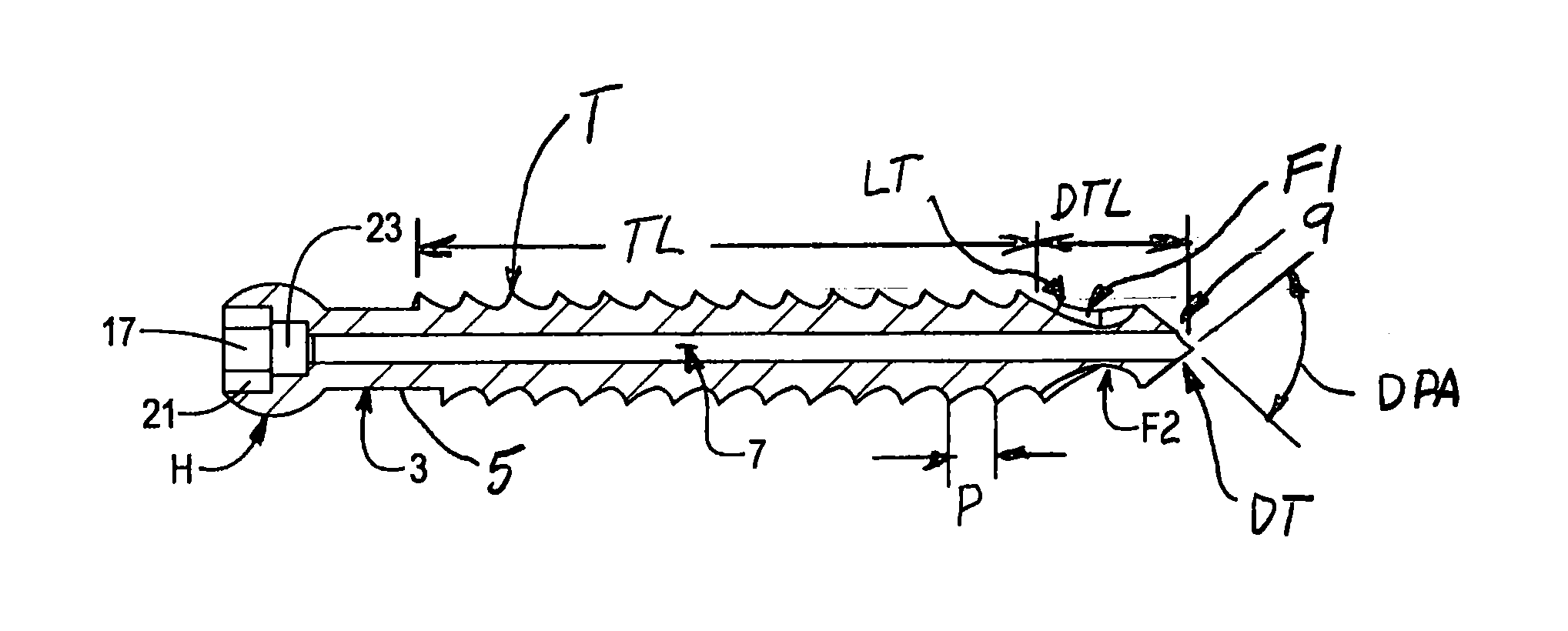
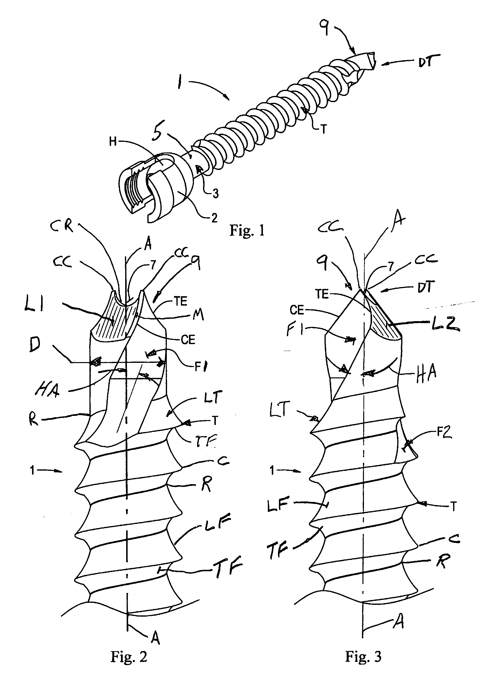
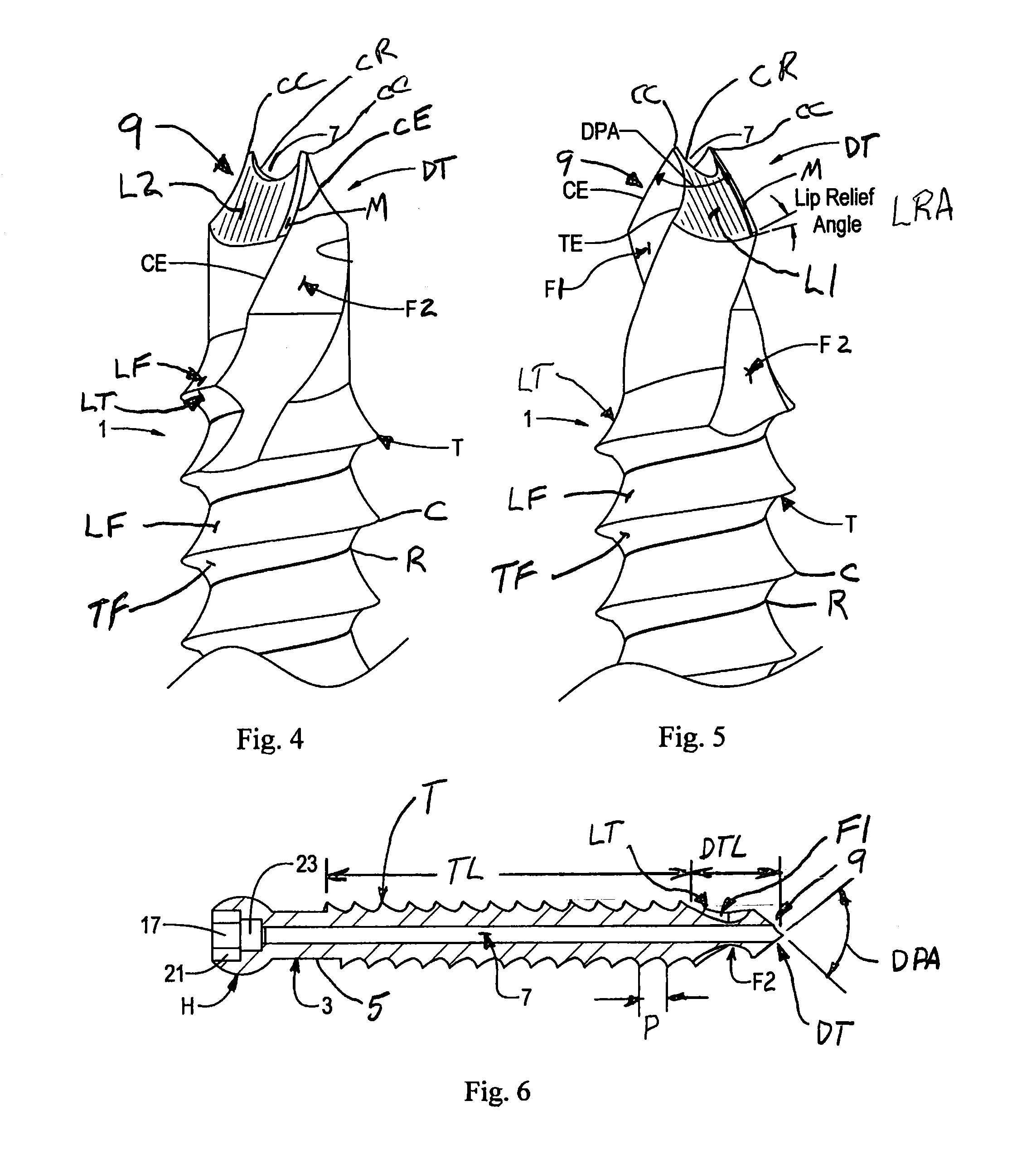
The present patent discloses a self-drilling, self-tapping bone screw that can be used to securely purchase bone in both the proximal and distal cortical margins of the sacrum without stripping the threads formed by the screw in the more proximal cancellous bone or cortical bone. This screw avoids a step of tapping threads in the bone structure, increasing surgeon's productivity and decreasing operating room times. The screw has a shank with a self-drilling, self-tapping tip at the distal end of the shank with plurality of helical bone screw threads along a portion of the shank. The drill tip has a unique design with a pair of diametrically opposed lands and helical flutes that act as cutting edges and form internal threads in the bone structure as the screw is rotatably driven into the bone structure. The length of the drilling tip is at least about the thickness of the proximal cortical bone layer to avoid stripping of the threads formed in the proximate cortical bone margin.

Problems solved by technology

In cases where the pedicle screws are placed in the sacrum, such constructs have been known to fail distally at the sacrum because the cancellous bone of the sacrum is significantly weaker than lumbar vertebrae body bone.
However, because in minimally invasive surgical (MIS) techniques the placement of such pedicle screws in the sacrum is typically performed over a guide wire and cannulated pedicle screws are blunt tipped, it is not possible to achieve such bicortical purchase of the screws in the sacrum.
Additionally a pilot hole cannot be drilled through the distal anterior cortical bone margin without risking the sharp tipped guide wire perforating organs in the pelvis.
Consequently the surgeon has to settle for unicortical fixation which is inherently weaker than the bicortical purchase of open techniques.

Method used


Image

  • Self drilling, self-tapping bone screw and method of installing for bicortical purchase
  • Self drilling, self-tapping bone screw and method of installing for bicortical purchase
  • Self drilling, self-tapping bone screw and method of installing for bicortical purchase

Examples


Embodiment Construction

[0037]Referring now to FIG. 1, a self-drilling, self-tapping bone screw, such as a pedicle screw, of the present disclosure is illustrated in its entirety by reference character 1. Screw 1 is a fully cannulated screw that has a part-spherical proximal driving head H for the attachment of a poly-axial saddle 2 (shown in phantom) or other accessory that is conventionally used in spinal surgery. The part-spherical head H allows the saddle 2 or other such appliance to be solidly mounted on the screw, but yet allows the saddle to readily swivel with respect to the screw. Those skilled in the art will recognize that head H and saddle 2 may be of different designs or shapes and may serve different purposes. Screw 1 has a shank, as generally indicated at 3, extending distally from the head. A portion of the shank 3, as indicated by the dimension labeled as thread length TL in FIG. 6, has threads T formed or machined therealong. As indicated at 5, the proximal portion of the shank between th...


PUM

PropertyMeasurementUnit
Angleaaaaaaaaaa
Angleaaaaaaaaaa
Thicknessaaaaaaaaaa

Abstract

A self-drilling, self-tapping bone screw is described in which the bone screw has a drill tip free of threads and having a length at least as great as about the thickness of a proximal cortical bone layer, with the drill tip having opposed lands and a helical flute between each of the lands with each of the lands having a cutting edge configured to cut bone as the drill tip is rotated into the bone with the flutes conveying the bone debris away from the drill tip, where a lead thread begins to self-tap internal threads in the proximal cortical bone layer after the drill tip has drilled through the proximal cortical bone layer so as to avoid stripping the threads formed in the bone layer. A method of installation is also disclosed.

Description

CROSS-REFERENCE TO RELATED APPLICATIONS[0001]This is a continuation-in-part of my non-provisional U.S. patent application Ser. No. 14 / 148,270, filed on Jan. 6, 2014, which is incorporated herein by reference in its entirety. This application claims priority to my U.S. Provisional Patent Application No. 61 / 791,287, filed on Mar. 15, 2013, which is herein incorporated by reference in its entirety.STATEMENT REGARDING FEDERALLY SPONSORED RESEARCH OR DEVELOPMENT[0002]Not ApplicableBACKGROUND OF THE DISCLOSURE[0003]This disclosure relates to a self-drilling and self-tapping bone screw, and in particular to self-drilling, self-tapping, fully cannulated fenestrated and non-fenestrated bone screws, and even more particularly to such self-drilling, self-tapping pedicle screws. This disclosure further relates to methods of installing such bone screws in a variety of surgeries including, but not limited to spine surgery. However, the methods of this disclosure will be described for use with spi...

Claims


Application Information

Patent Timeline
IPC IPC(8): A61B17/86
CPCA61B17/8635A61B17/863A61B17/864A61B17/1655A61B17/7035A61B17/7082A61B17/7098F16B25/0015F16B25/0084F16B25/103Y10T29/49826A61B17/1615A61B17/84A61B17/8625B23B2260/124B65D7/045B65D11/06B65D11/24B65D21/0219B65D21/022B65D43/0231B65D2543/00027B65D2543/00092B65D2543/00222B65D2543/00277B65D2543/00296B65D2543/00537F16B25/00F16B25/0031F16B25/0052F16B25/10Y10T29/49963
Inventor POULOS, NICHOLAS
Owner POULOS NICHOLAS
Learn More