
Laser obstacle detector

a laser and obstacle technology, applied in the field of laser obstacle detectors, can solve the problems of inability to realize real breakthroughs in practical and affordable mobility devices, limited use, and people in considerable danger, and achieve the effect of reducing computing time and powerful computers

Active Publication Date: 2014-09-18
GOSZYK KURT A
View PDF3 Cites 14 Cited by
  • Summary
  • Abstract
  • Description
  • Claims
  • Application Information

AI Technical Summary

Benefits of technology

The invention is a device that can detect obstacles using a laser and a camera. The laser creates a pattern of lines on the obstacle, which the camera records. The device then uses image processing to remove background noise and detect edges. It can also determine if the laser pattern is distorted and alert the user with a visual or sensory signal. The device can also store patterns for comparison with new images to better identify obstacles.

Problems solved by technology

Although the blind and visually impaired have made great strides in education, employment, and information access, they have not benefited from any real breakthroughs in practical and affordable mobility devices that facilitate safe and independent travel outside of the home.
Although users may become very adept with a “pure” mechanical device, such as the traditional “long cane” or “white cane,” there are inherent limitations to its use, most notably the requirement that the device actually touch the obstacle by a “swipe” or a “thrusting” or “probing” technique.
This fact can put the person in considerable danger, even if successfully employed since typically, the probing motions are limited to close, ground-level obstacles.
Scanning with an ultrasound wide beam will not easily find openings, especially from a distance.
Wind and temperature changes affect the ultrasound beam and will give false distances and alarms.
If approaching an obstacle at less than 45° degrees, the ultra sonic signal tends to miss the obstacle because it is reflected away from smooth surfaces (e.g., smooth walls, and some smooth, contoured obstacles) and is a known disadvantage of ultra sonic detection devices in general.
Thus, the typical ultra-sonic devices that have been marketed are simply not reliable enough to inspire the trust necessary for a blind person to rely on the sensory signals (i.e. sounds, musical notes, etc.) thereby negating one of the major positives to be expected from a primary visual assistance device, namely, a growing sense of self-confidence and trust in the device.
Use of guide or companion dogs has provided some people with increased mobility and self-sufficiency, but this benefit is limited to a small potion of the overall potential patient population for many reasons.
Although guide dogs enjoy tremendous support among the general public as well as among the visually impaired population, there are a significant number of people who cannot use a guide dog or who cannot cope with some of the disadvantages inherent in using a “sight instrument” with independent action capabilities.
Many people are allergic to, or don't like, dogs or their feed / grooming aids, and caring for the dog presents stresses and challenges that many vision and mobility impaired people are not able to handle without constant assistance from a sighted person.
Dogs, just like people, have personalities which can be difficult to “match” and they also get sick, infirm and die, creating serious emotional and practical challenges.

Method used


Image

  • Laser obstacle detector
  • Laser obstacle detector
  • Laser obstacle detector

Examples


Embodiment Construction

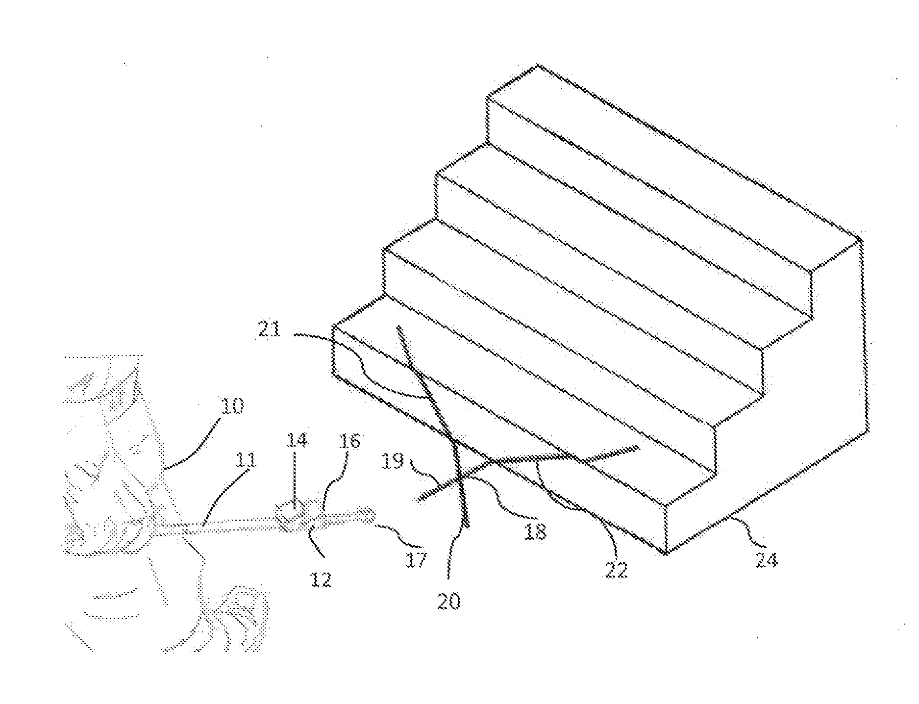
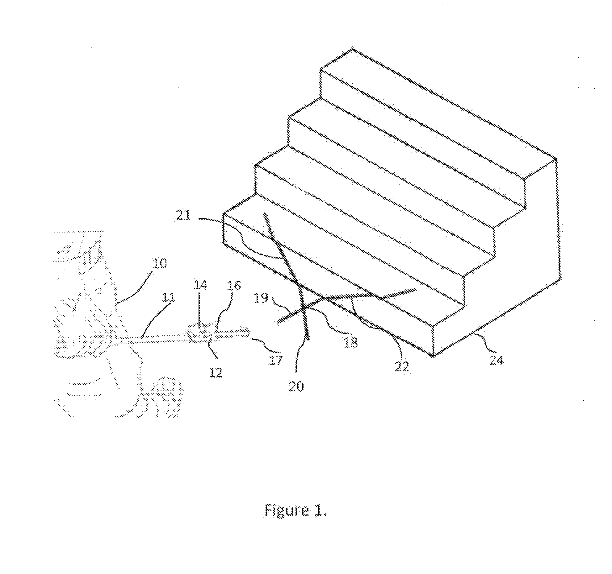
[0023]Although obstacle detection can be used in a variety of embodiments including human hand-held games, vehicles, wheelchairs, robots, and a number of moving objects, one preferred embodiment is shown in FIG. 1 as a walking cane for the blind and visually impaired.

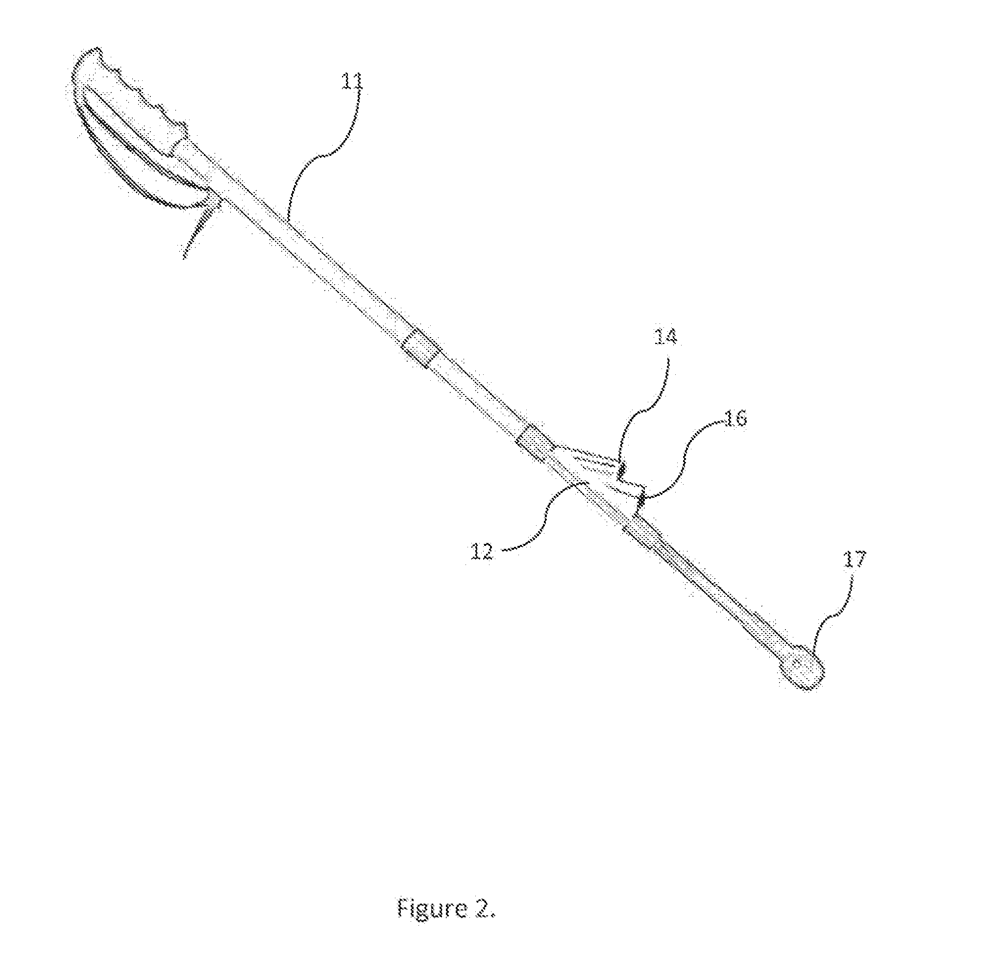
[0024]Referring to FIG. 1, a blind or visually impaired person 10 carries a cane 11 as he walks. The cane typically is constructed from light weight metal, fiberglass or plastic with is tip 17 at the bottom end to help the person “feel” his way along. Attached to the top side of the cane 11, detector system 12 consists of en infrared laser projector 14 and solid state camera assembly 16. Other elements of detector system 12 are referenced in the discussion relevant to FIG. 3. The infrared light spectrum is used for eye safety, unobtrusiveness and for easier detection by a solid state camera imager. An infrared laser beam pattern 18 is projected from the projector 14 in front of the person 10. The laser pattern is aligne...


PUM


Abstract

The present invention provides a device for assisting a person in determining the presence or identity of obstacles in the person's path, characterized by a housing, a laser projector for generating a laser pattern in a surface in said person's path, a receiver for at least receiving a plurality of images of the laser pattern reflected from the surface and for generating a signal corresponding to said laser pattern reflection and a processor for processing said signal to at least determine the presence or identity of an object, and a warning generator for generating a warning to the person. The present invention also provides a method for assisting a person in determining the presence of an object in a person's path comprising generating a laser pattern comprising a plurality of laser lines on a surface, distinguishing between one or more straight line segments in the laser pattern and distorted line segments of said laser pattern after they are reflected from said surface and evaluating the distortions in said line segments of said laser pattern to determine the presence or identity of an object in the person's path. The present invention can be used to assist the visually impaired in seeing objects in their path or can be used by a sighted user in game play or at night for detecting obstacles. Some of the functions of the present device can be provided in a smart phone which can be adapted with a laser projection as a separate attachment or as part of the smart phone circuitry.

Description

CROSS REFERENCE TO RELATED APPLICATION[0001]This application claims the benefit of priority to U.S. Provisional Application Ser. No. 61 / 509,788, filed on Jul. 20, 2011, which is herein incorporated by reference.BACKGROUND[0002]For the blind or visually impaired, the current state of technology, besides guide dogs, includes alternative devices based on mechanical designs (i.e. various types of canes and guide mechanisms) or ultra-sonic technologies. Although the blind and visually impaired have made great strides in education, employment, and information access, they have not benefited from any real breakthroughs in practical and affordable mobility devices that facilitate safe and independent travel outside of the home.[0003]Although users may become very adept with a “pure” mechanical device, such as the traditional “long cane” or “white cane,” there are inherent limitations to its use, most notably the requirement that the device actually touch the obstacle by a “swipe” or a “thru...

Claims


Application Information

Patent Timeline
Patent Type & Authority Applications(United States)
IPC IPC(8): G01S17/93H04M1/02G08B21/02H04M1/72481
CPCG01S17/93H04M1/0272H04M1/0264G08B21/02A61H2201/0153A61H2201/0184A61H2003/063A61H2003/065A61H2201/5092H04M2250/52A61H3/061H04M1/72481
Inventor GOSZYK, KURT A.
Owner GOSZYK KURT A
Learn More