
Distributed two-step clock

a two-step clock and clock technology, applied in the direction of time division multiplex, synchronisation arrangement, electrical equipment, etc., can solve the problems of inability to accurately distribute two-way time-transfer protocols, inability to ensure the accuracy of two-way time-transfer protocols, and inability to ensure the accuracy of time-transfer protocols, so as to avoid or mitigate the effect of possible asymmetry and packet delay variation in the network

Active Publication Date: 2014-09-18
MICROSEMI FREQUENCY & TIME
View PDF3 Cites 38 Cited by
  • Summary
  • Abstract
  • Description
  • Claims
  • Application Information

AI Technical Summary

Benefits of technology

This patent is about methods and devices used to transfer time accurately, while minimizing the delay and difference in timing that can occur in networks. Overall, this patent aims to create a system that can make precise time transfers more reliably.

Problems solved by technology

However, these implementations, based on existing standards and conventions are only suitable for time alignments on the order of (several) milliseconds.
However, even where full on-path support is provided, the asymmetry in the connecting links remains as a dominant source of time transfer inaccuracy.
In all cases, the accuracy of two-way time-transfer protocols is adversely affected by asymmetry introduced by the communications network connecting the two network elements, including asymmetry in the physical medium, asymmetry in the construction of the forward and reverse paths in the network elements, and other sources.
But because forward and reverse physical paths are often different in coupled network elements, they are typically not symmetric.
This is a source of asymmetry.
In all packet-based timing transfer methods, including PTP and NTP, there are two principal sources leading to synchronization error.
PDV, on the other hand, is an expected phenomenon in packet networks and contributes to asymmetry as well as to dynamic time alignment error.
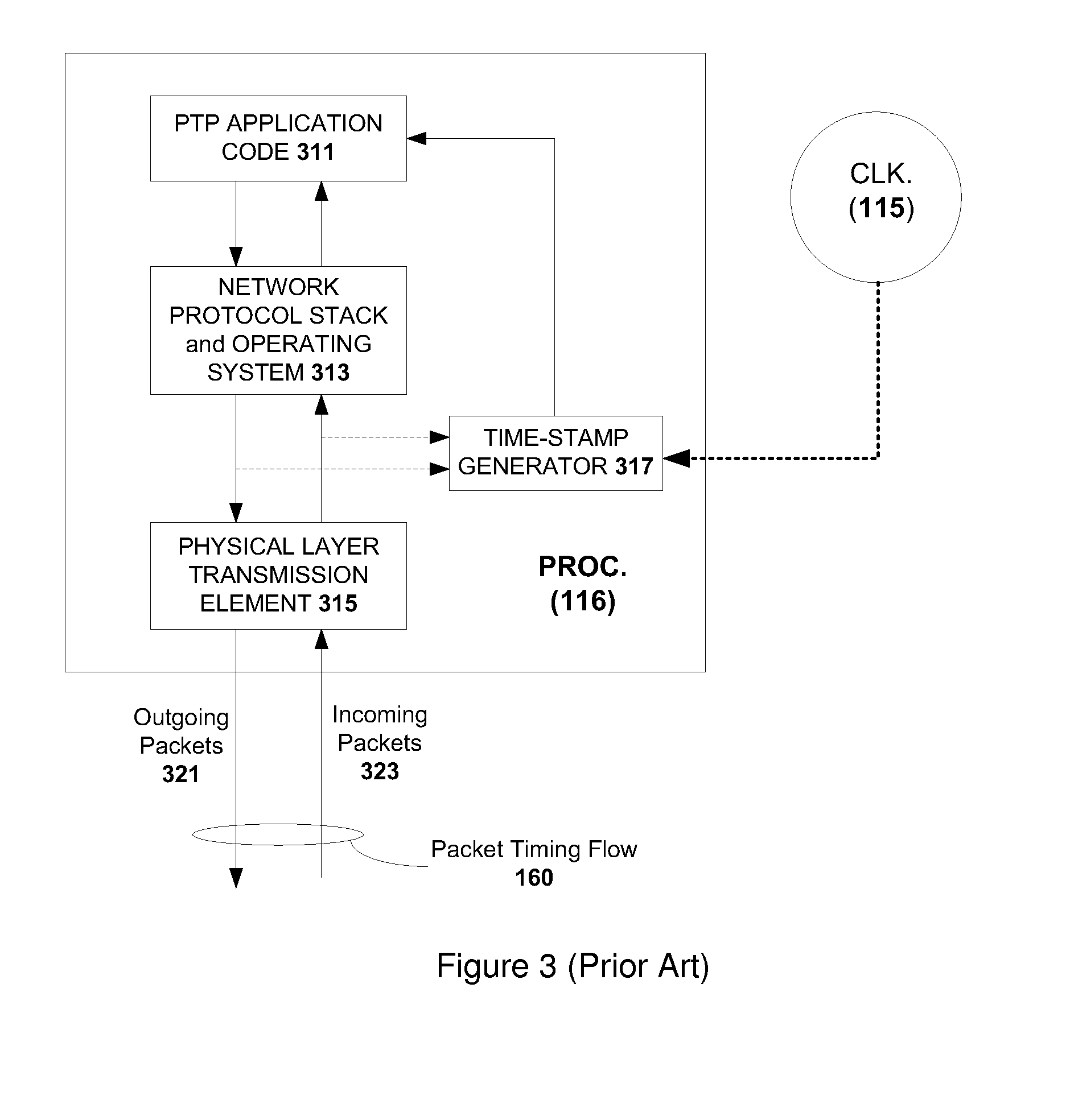
However, such methods do not address the deleterious impact of asymmetry in the physical plant (i.e. cables and physical layer transmission).

Method used


Image

  • Distributed two-step clock
  • Distributed two-step clock
  • Distributed two-step clock

Examples


Embodiment Construction

[0027]Embodiments of the invention described here provide robustness and relative insensitivity to network packet delay variation (PDV) and network transit-delay asymmetry. By logically placing the timing critical functions of the master close to the slave, the PDV and transit-delay asymmetry introduced by the network can be defeated, as there is typically less noise added between closer network elements. Here, “closer” refers to less logical network distance in terms of the number of intervening switches and / or routers. In one embodiment, the timing functions of the master may be placed closer to the slave using a Remote Time-Stamp Generator, located in the network between the master and the slave, and whose time reference serves as a proxy for the time reference of the master. More specifically, time-of-traversal of packets (specifically, SYNC messages and DELAY_REQUEST messages in PTP) at the Remote Time-Stamp Generator may be used as proxies for the time-of-departure of SYNC mes...


PUM


Abstract

The present invention generally relates to methods and apparatus for precision time transfer wherein the inherent packet delay variation and possible asymmetry introduced in networks is avoided or mitigated. In one embodiment, the timing functions of a master device may be placed closer to a slave device using a Remote Time-Stamp Generator, located in the network between the master and the slave, and whose time reference serves as a proxy for the time reference of the master. Time-of-traversal of packets at the remote time-stamp generator may be used as proxies for the time-of-departure and the time-of-arrival of certain messages at the master. Such proxy times may be used to synchronize the slave with the master, particularly if the master and the Remote Time-Stamp Generator are both synchronized with a Global Navigation Satellite System (GNSS) source.

Description

CROSS-REFERENCE TO RELATED APPLICATIONS[0001]This application claims priority to U.S. provisional application having Ser. No. 61 / 789,957, filed on Mar. 15, 2013, which is hereby incorporated by reference in its entirety.BACKGROUND OF THE INVENTION[0002]1. Field of the Invention[0003]Embodiments of the present invention relate generally to time and frequency alignment systems operating over packet-switched communications networks and, more specifically, to methods and apparatus for precision time transfer where the inherent packet delay variation and possible asymmetry introduced in networks is avoided or mitigated.[0004]2. Description of the Related Art[0005]It has been recognized that synchronizing network elements in communications networks to a high level of precision enables the provision of advanced services. In fact, time and frequency alignment is essential to certain types of systems. For example, accurate time alignment is required by cellular networks, services carried out...

Claims


Application Information

Patent Timeline
IPC IPC(8): H04W56/00
CPCH04W56/0045H04J3/0667H04J3/0673H04W56/0015
Inventor ZAMPETTI, GEORGE P.
Owner MICROSEMI FREQUENCY & TIME
Learn More