Concentrating solar collector and pre-formed fresnel array reflector panel

Active Publication Date: 2014-09-18
HANSEN HAROLD TRAVIS
View PDF7 Cites 26 Cited by
  • Summary
  • Abstract
  • Description
  • Claims
  • Application Information

AI Technical Summary

Benefits of technology

The solar collector described in this patent provides a convenient and easy-to-use system for collecting solar energy. It includes a nested frame and folding reflector panels that can be adjusted easily to focus the sun's energy on a receiver. The design also includes a flat, safe surface for cooking and a reflector support panel that can hold a larger array of reflectors in a compact way. The collector is aligning to shield the user from glare and can also hold larger pots and pans for direct heating. The technical effects of this design include improved efficiency, ease of use, and flexibility in the variety of pots and pans that can be heated.

Problems solved by technology

Energy consumers in some areas have installed local systems, which avoid the transmission losses inherent in distribution from centralized plants, but usually operate at the lower efficiency of photovoltaic (PV) conversion.
Many less-developed areas of the world have seen significant deforestation and environmental degradation as a result of people using traditional fuels for cooking fires.
Efforts have been made to encourage use of solar cookers in these areas, with limited success.
Populations with a lifestyle and economy that are more dependent upon fossil fuels will suffer greater stress, as those fuels become more costly.
Development and implementation of apparatus for local scale, distributed solar thermal energy collection and use confronts many of the same difficulties as large-scale installations.
Apparatus for local concentration of solar energy offers a greater range of uses than non-concentrating solar collectors, but presents a greater challenge for design and cost efficiency.
Beyond the costs of materials, manufacturing and maintenance, development of apparatus suitable for home, farm, or small business use also contends with issues such as space requirements, safety, portability and ease of use.
However, the incident angle of sunlight to a lens or reflector that is fixed in position will change continuously as the earth turns, thus changing the resulting reflective angle.
Maintenance of automated mechanical solar tracking has been a significant cost barrier for large, centralized solar thermal electric generation facilities.
Concentrators with individually moving reflectors, even at a smaller scale, require a complicated mechanical infrastructure.
In dish type concentrators the receiver and the user can cast shadows over reflector area in some designs, reducing efficiency.
Cooking vessels positioned over reflectors, or that must be lifted over them are more likely to may spill and spatter food upon the reflectors, also reducing efficiency.
The Ao Chi F800 reflective surface is not very durable, being a metallized plastic film.
The receiver sits above the reflector area, with the resultant problems of spillage.
This unit is also limited in its reflector size and power, in favor of user access to the receiver.
User access to the receiver for cooking-related activity becomes more problematic as the size of reflectors is increased for greater concentrator capacity.
Similarly, the challenge of providing a convenient way to perform manual solar tracking adjustments grows in proportion to reflector area.
However, these implementations still require costly, laborious and difficult fabrication techniques, or lack a surrounding structure that provides good ease of use.
Fabrication and assembly is costly, the paraboloid section shape is rather bulky, and the user approach to the focus becomes difficult when the sun is lower in the sky.
The location of the mechanism is inconvenient and possibly hazardous to the user, as it requires reaching over the focal area past a hot cooking vessel.
Azimuth adjustments require tilting the entire apparatus to pivot it upon its one axle or skidding its base foot sideways, risking spillage from the vessel at the focal area.
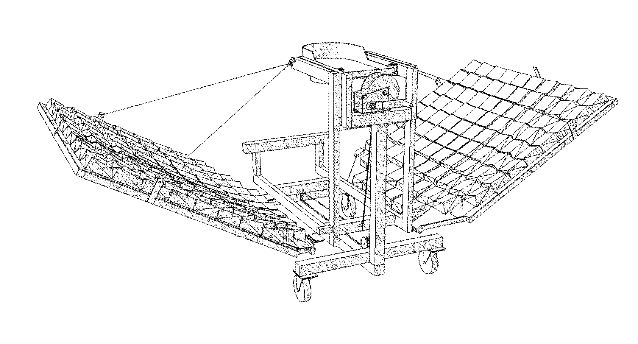
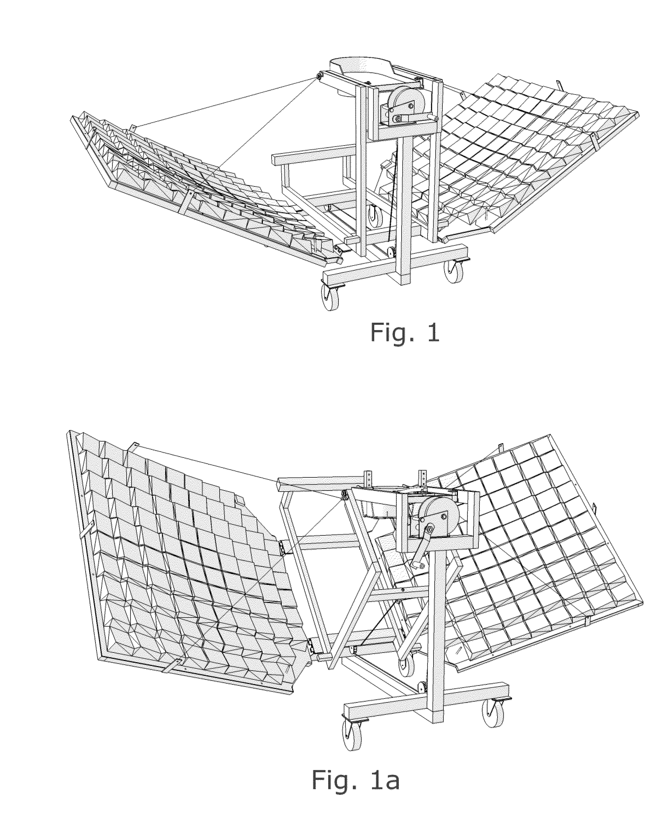
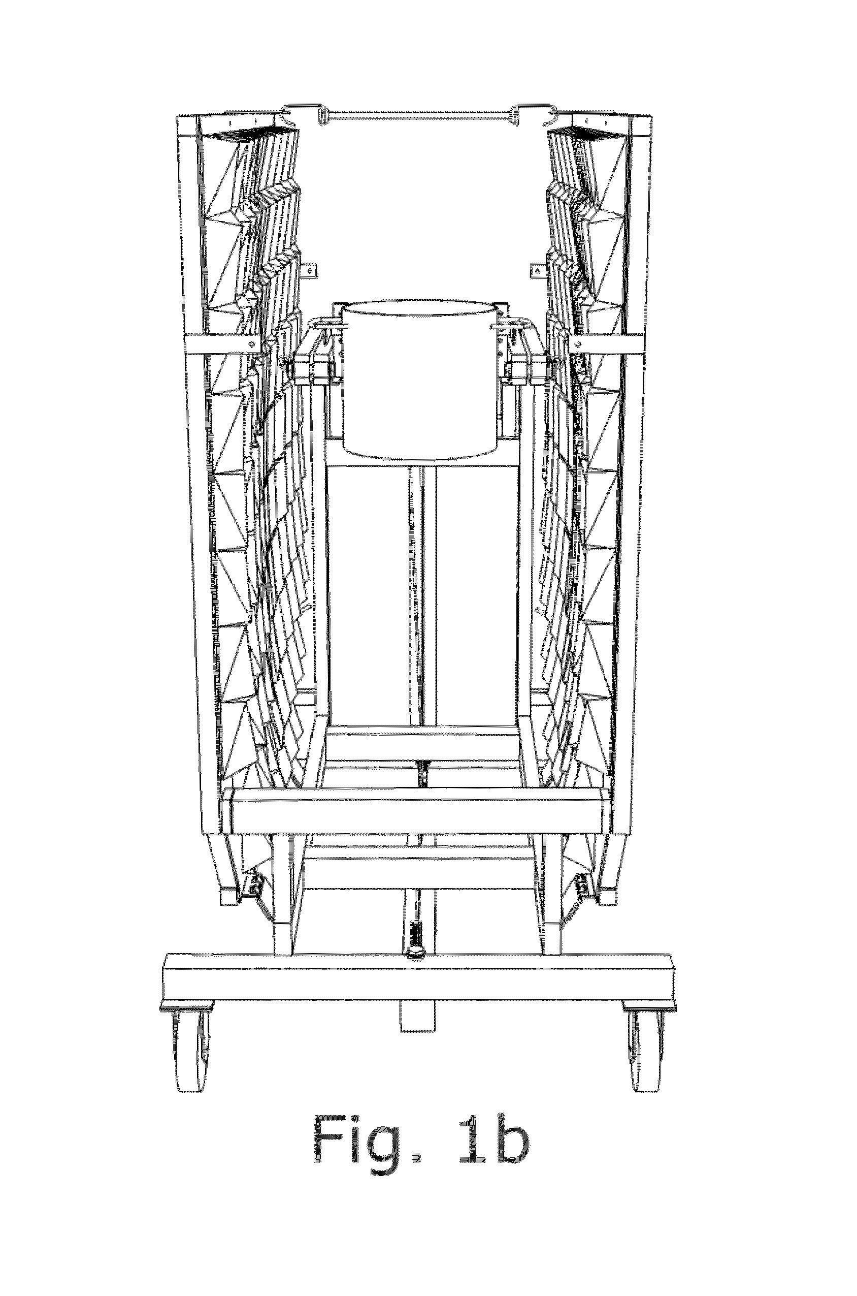
The Iron Butterfly's reflector arrays are in a trapezoidal shape that does not maximize reflector aperture relative to outer dimensions of the apparatus, in use or in the (folded) storage position.
Mounting and aligning the Fresnel array of mirrors requires a complex and heavy backing structure.
A backing plate for each flat reflector in the array must be aligned and attached to framing with individual welded supports, making fabrication laborious and costly, and adding substantially to the weight of the apparatus.
Though some success has been demonstrated, the difficult and laborious multi-step process is vulnerable to error and imprecision at various stages.
But flexing and distortion of the non-braced portion of the carriage may reduce focal precision and usable energy, and the facilitation of user proximity to the focal area increases the likelihood of operator exposure to concentrated solar energy.
The bracing location also limits the range of carriage travel; with the sun directly overhead, proper focus requires compensatory tilting of the entire apparatus.
The Iron Butterfly's spooling mechanism for cable-controlled adjustment of reflector altitude is located near the focal area, similar to the Papillon design, so use is difficult and possibly hazardous.
However, positional adjustments are difficult and uncomfortable to perform accurately in this manner, further compromising ease of use and general efficacy of the concentrator.
Suspension lines to hold the Iron Butterfly's reflector panels in operating position are attached to the panel carriage asymmetrically and lack a means to maintain equal tension between them.
This may contribute to flexion of the reflector panels with consequent focal imprecision.

Method used


Image

  • Concentrating solar collector and pre-formed fresnel array reflector panel
  • Concentrating solar collector and pre-formed fresnel array reflector panel
  • Concentrating solar collector and pre-formed fresnel array reflector panel

Examples


example embodiments

Features of Example Embodiments

[0037]What follows describes two exemplary embodiments of the solar collector (see FIG. 1, FIG. 2b), with some parts and aspects of the invention directed toward those embodiments, for use as a solar cooker. Many uses other than cooking are possible; but cooking is likely to be the most common use.

[0038]A flattop receiver can be used as a griddle, or used with flat-bottomed cooking vessels resting on it to be heated by contact similar to a smooth-top stove. Concentrating reflector panels are shown in open, operating position (see FIG. 1, FIG. 1a). The reflector carriage and reflector panels are also shown positioned for storage (see FIG. 1b). The main frame is shown with a rolling chassis (see FIG. 2), so that the apparatus is easily moved over a firm, smooth surface, or installed to a fixed-location pivot (see FIG. 2b). There is a novel cable system for convenient manual altitude adjustment of reflectors (FIG. 3). Most materials used in the preferred ...


PUM

PropertyMeasurementUnit
Areaaaaaaaaaaa
Altitudeaaaaaaaaaa
Perimeteraaaaaaaaaa

Abstract

A concentrating solar collector is disclosed, comprising: A nested main frame and reflector carriage with vertically folding reflectors in a Fresnel-type array, using a one-piece pre-formed panel. A hand-winch operated cable system provides for a full range of reflector altitude adjustment. A one-piece, pre-formed reflector panels provide for pre-aligned mounting of reflective material. An alignment guide allows assessment of solar tracking alignment without gazing toward the focal area. A flattop receiver for heating smaller flat-bottomed pots and pans or for direct griddle cooking, and an adjustable rack for positioning larger cooking vessels in the focal area for use as direct receivers. Also described is a method for making one-piece, pre-formed reflector panels. One embodiment has a lower frame portion substantially forming a rolling chassis. An additional embodiment describes lower frame structure for a fixed location installation.

Description

CROSS-REFERENCE TO RELATED APPLICATIONS[0001]Not ApplicableSTATEMENT REGARDING FEDERALLY SPONSORED RESEARCH OR DEVELOPMENT[0002]Not ApplicableREFERENCE TO SEQUENCE LISTING, TABLE OR COMPUTER PROGRAM LISTING[0003]Not ApplicableBACKGROUND OF THE INVENTION[0004]1. Field of the Invention[0005]This invention relates to distributed-scale apparatus for concentration and collection of solar energy.[0006]2. Discussion of Prior Art[0007]As non-renewable energy resources such as coal, oil, and natural gas become more scarce and costly to obtain, the need for practical ways to utilize renewable energy sources grows. Solar energy investment in industrialized regions has been influenced by preexisting patterns and infrastructure for distribution of electrical power from large, centralized facilities. Several large facilities for centralized solar thermal generation of electric power have been completed in the US and other countries. These have typically used a great number of ground-based heliost...

Claims


Application Information

Patent Timeline
IPC IPC(8): F24J2/02F24J2/54F24J2/38F24S20/30F24S23/70F24S50/20
CPCF24J2/02F24J2002/5458F24J2002/108F24J2/542F24S20/30F24S30/452F24S2023/872F24S2030/133Y02B40/18Y02E10/47Y10T29/49355Y02A40/926
Inventor HANSEN, HAROLD TRAVIS
Owner HANSEN HAROLD TRAVIS
Why Eureka
Try Eureka