
Communication device and non-transitory computer-readable storage medium storing program for controlling the communication device

a communication device and computer-readable storage technology, applied in computing, digital output to print units, instruments, etc., can solve the problems of capacitance type sensor capacitance type erroneous activation, radio wave used in near field communication and electric field used in touch sensor mutual interference, etc., to reduce the detection sensitivity of the touch sensor

Active Publication Date: 2014-09-11
BROTHER KOGYO KK
View PDF3 Cites 14 Cited by
  • Summary
  • Abstract
  • Description
  • Claims
  • Application Information

AI Technical Summary

Benefits of technology

The invention aims to solve the problem of mutual interference between the radio wave used in near field communication and the electric field used in touch sensors of capacitance type in communication devices. This can suppress interference and improve the accuracy and reliability of the touch sensors.

Problems solved by technology

However, there may be a risk that a radio wave used in the near field communication and an electric field used in the touch sensor of capacitance type mutually interfere.
In particular where an antenna portion for the near field communication and the touch sensor of capacitance type are disposed adjacent to each other in view of operability for the user, the possibility of occurrence of the mutual interference of the radio wave and the electric field becomes considerably high.
In a case where the mutual interference between the radio wave and the electric field occurs, the near field communication is unlikely to be established or misactivation of the touch sensor of capacitance type may be caused, in other words, the touch sensor of capacitance type may be erroneously activated.
Accordingly, the mutual interference between the radio wave and the electric field is not desirable.

Method used


Image

  • Communication device and non-transitory computer-readable storage medium storing program for controlling the communication device
  • Communication device and non-transitory computer-readable storage medium storing program for controlling the communication device
  • Communication device and non-transitory computer-readable storage medium storing program for controlling the communication device

Examples


modified example

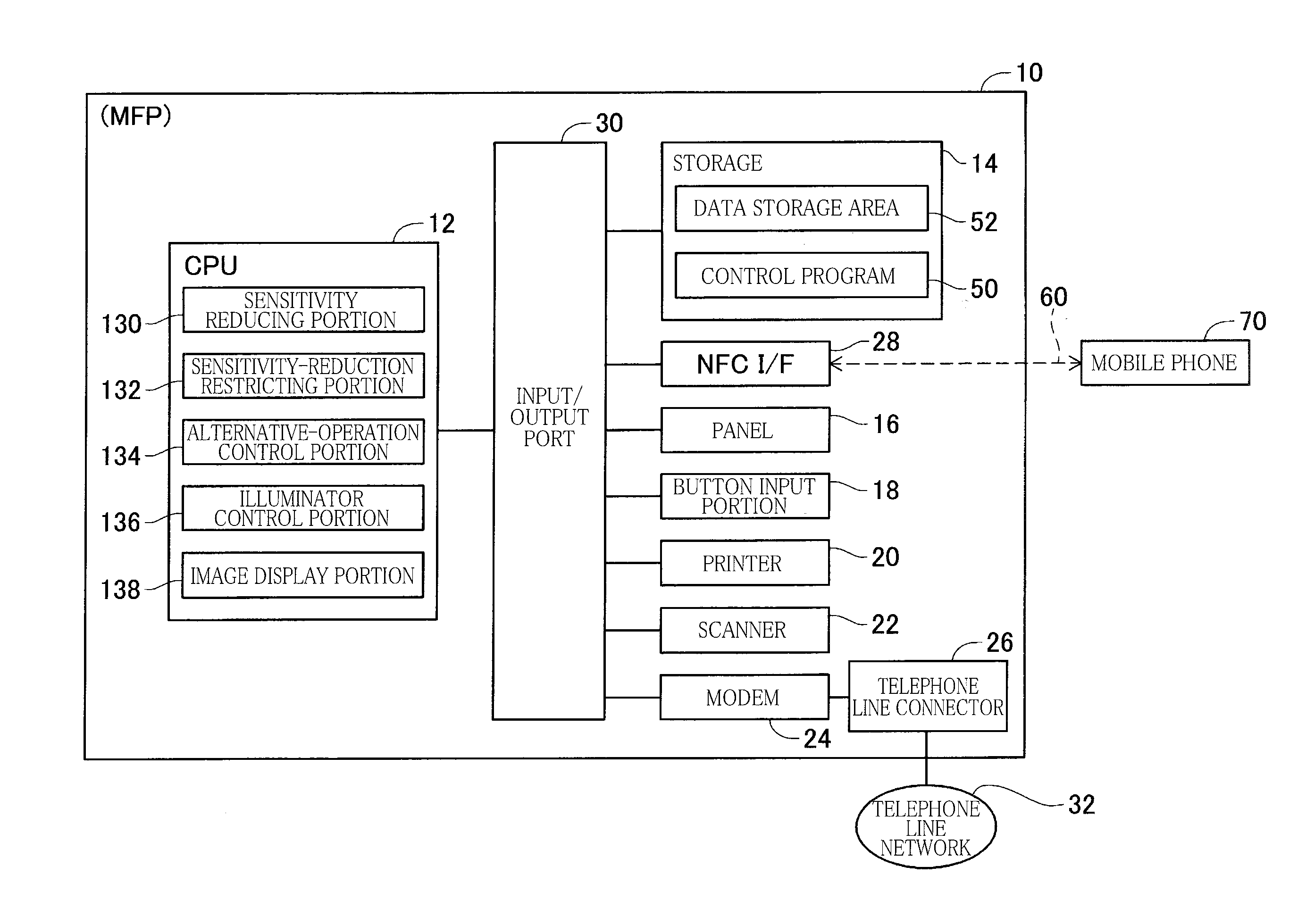
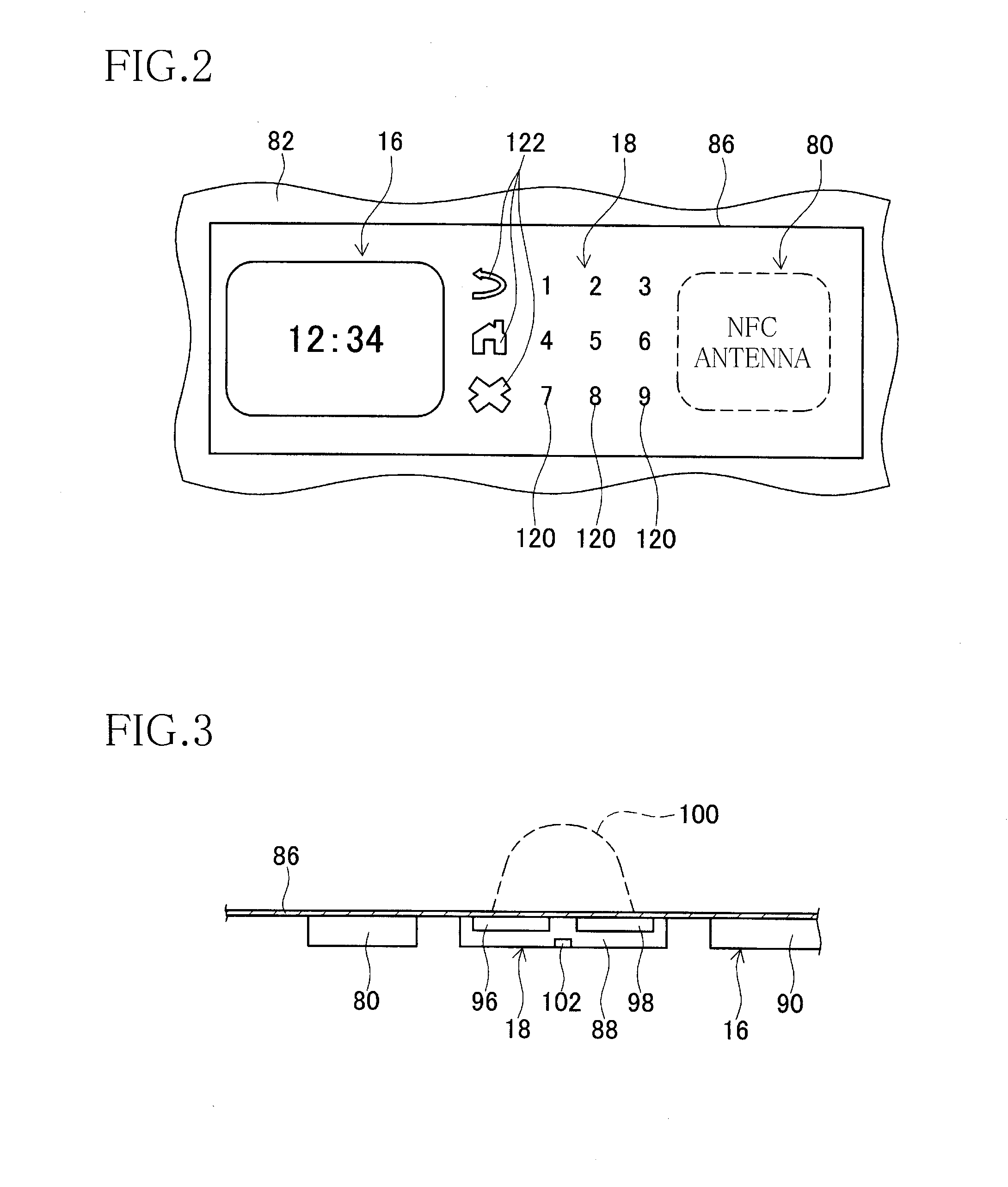
[0062]It is to be understood that the present invention is not limited to the details of the embodiment illustrated above, but may be embodied with various changes and modifications, which may occur to those skilled in the art. In the illustrated embodiment, the mutual interference between the radio wave 110 of the mobile phone 70 and the electric fields 100 of the touch sensors 88 is suppressed by interrupting electrification to the touch sensors 88 when the mobile phone 70 is brought near to the MFP 10. The mutual interference between the radio wave 110 and the electric fields 100 may be suppressed by weakening the electric fields 100 of the touch sensors 88 according to a modified example shown in FIG. 9, for instance.

[0063]As shown in FIG. 9, the electric field 100 generated between the transmission electrode 96 and the reception electrode 98 may be weakened by decreasing an amount of the electric current supplied to the transmission electrode 96 of the touch sensor 88. The arra...


PUM


Abstract

A communication device, including: a touch sensor configured to detect a touch or an approach of an input object by detecting a change in capacitance; a near field communicator configured to perform near field communication with an information processing terminal present in a communication area in which near field communication is possible, the information processing terminal being capable of performing the near field communication; and a controller configured to control the communication device in accordance with detection of the touch or the approach of the input object by the touch sensor, wherein the controller is configured to reduce detection sensitivity of the touch sensor for detecting the input object when the information processing terminal is in the communication area.

Description

CROSS REFERENCE TO RELATED APPLICATION[0001]The present application claims priority from Japanese Patent Application No. 2013-042614, which was filed on Mar. 5, 2013, the disclosure of which is herein incorporated by reference in its entirety.BACKGROUND OF THE INVENTION[0002]1. Field of the Invention[0003]The present invention relates to a communication device configured to perform near field communication with an information processing terminal and a non-transitory computer-readable storage medium storing a program for controlling an operation of the communication device.[0004]2. Description of Related Art[0005]There have been conventionally developed communication devices capable of performing near field communication with information processing terminals such as smartphones and tablet personal computers. In the near field communication, transmission and reception of data can be performed by merely bringing the information processing terminal near to the communication device. Some...

Claims


Application Information

Patent Timeline
IPC IPC(8): H04N1/00
CPCH04N1/00106H04N1/00381H04N2201/006H04N1/00204H04N1/00384H04N1/00408H04N1/00925H04N2201/0036H04N2201/0094
Inventor AOYAMA, KENTARO
Owner BROTHER KOGYO KK
Learn More