
Method of co-drawing hybrid incompatible materials

a technology of hybrid materials and preforms, applied in glass fiber products, glass reforming apparatuses, textiles and papermaking, etc., can solve the problems of limiting the choice of materials and applications of multi-material and multi-component fibers, affecting the performance of the ultimate device made with such multi-material fibers, and not being able to use the best of each class of materials

Active Publication Date: 2014-08-28
FLEX OPTRONIX TECH
View PDF9 Cites 6 Cited by
  • Summary
  • Abstract
  • Description
  • Claims
  • Application Information

AI Technical Summary

Benefits of technology

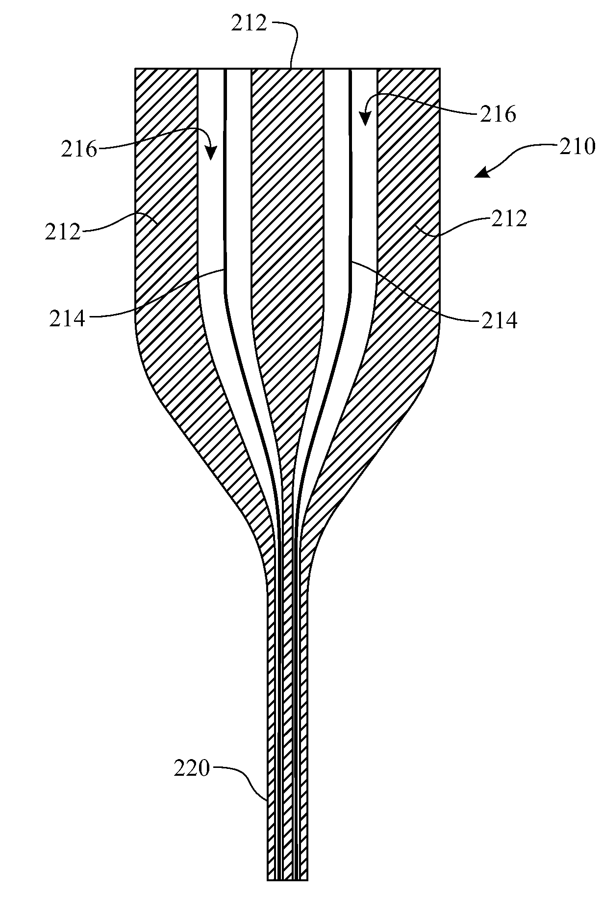
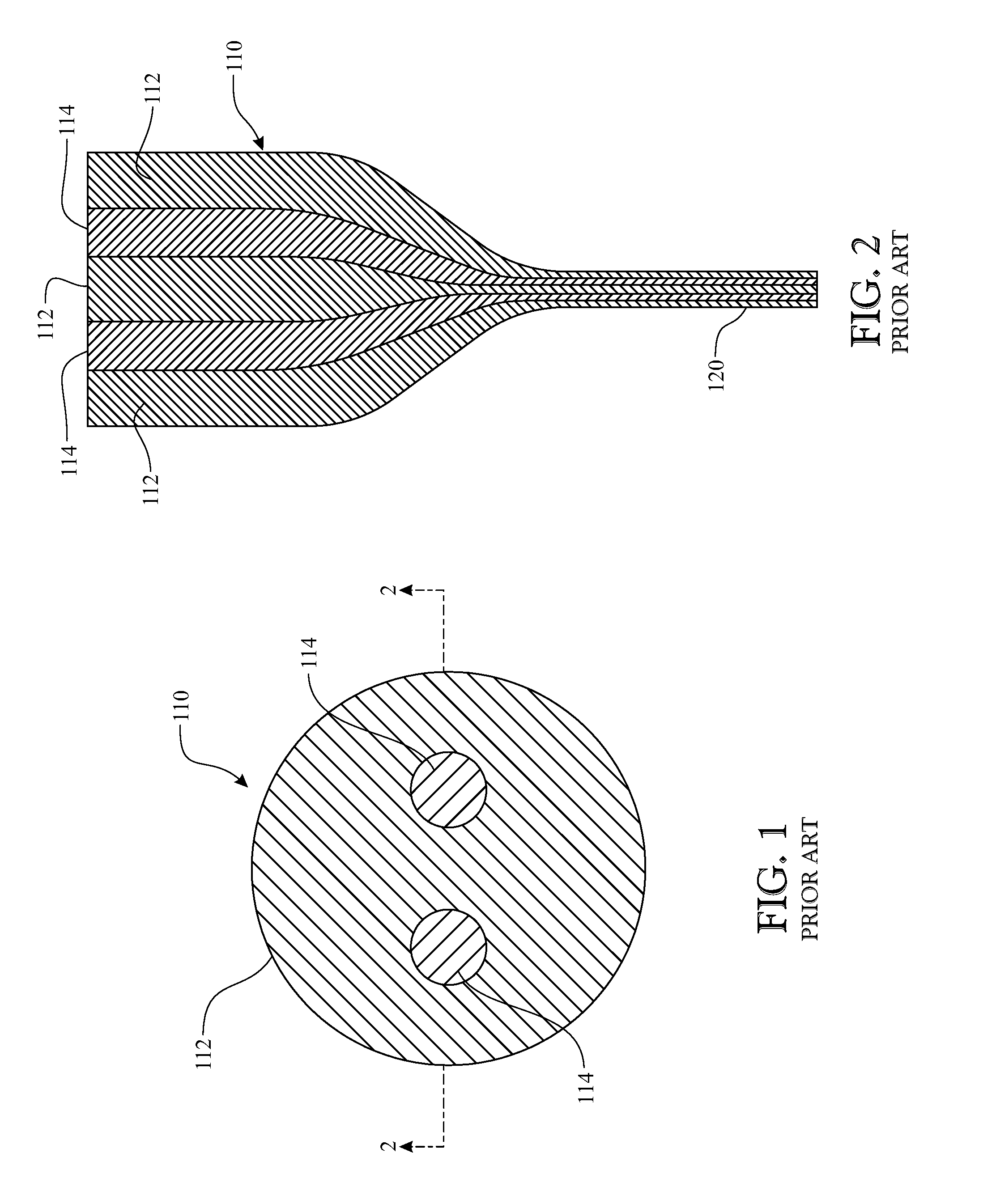
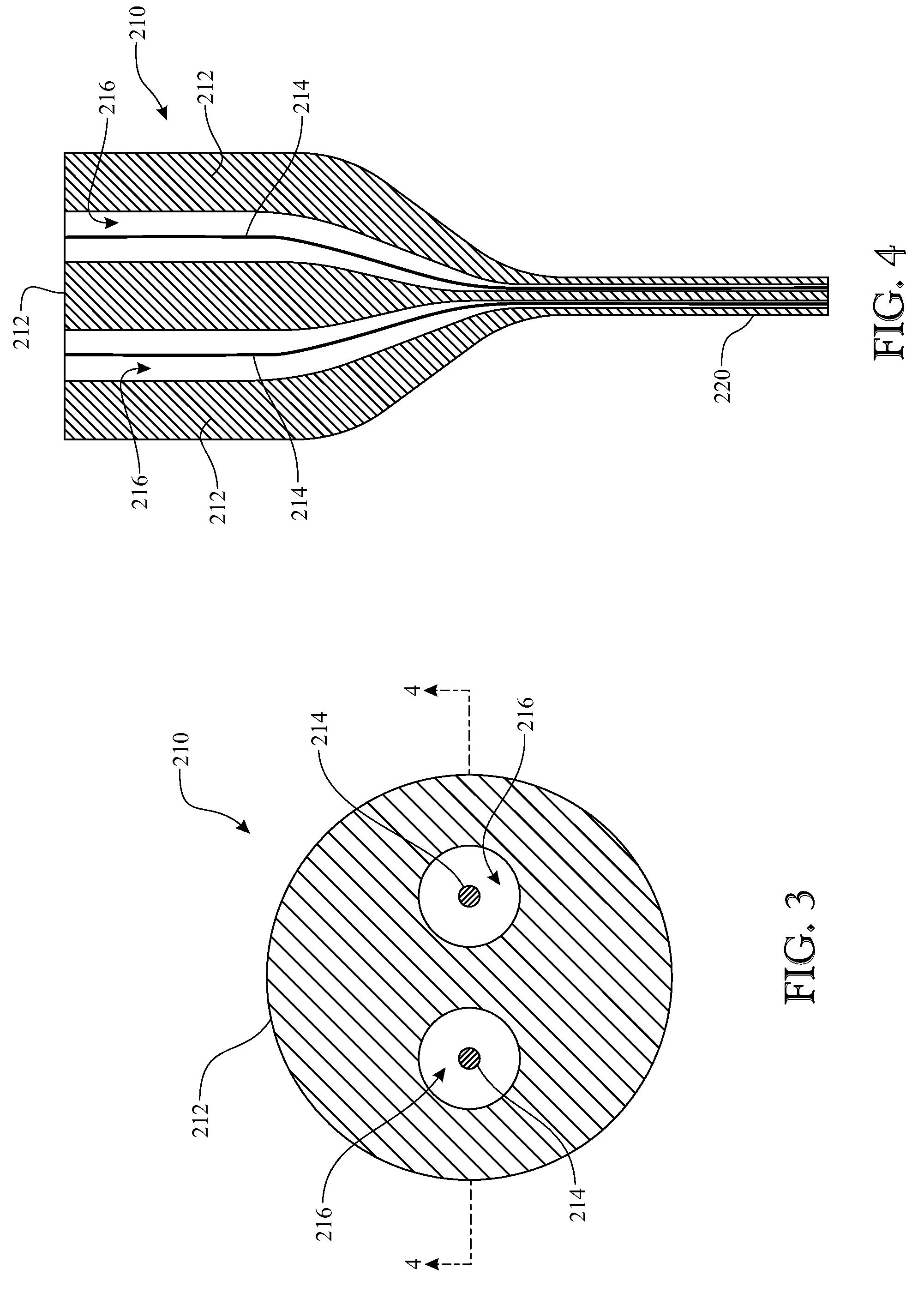
The present invention provides a method for co-drawing two or more different materials in the same preform. This involves inserting a second element into a channel in a preform body, which is then heated and drawn in a way that preserves the shape of the channel while the second element is reduced in size. This method allows for the creation of a continuous fiber comprising both first and second elements, without the need for a continuous supply of the second element. The invention can be used with either a motorized system or a low-friction system for feeding the second element into the thermal drawing process. Overall, this method allows for the efficient and controlled co-drawing of two or more materials in a preform, which could be useful in various applications such as manufacturing processes.

Problems solved by technology

This limits the choice of materials and applications of multi-material and multi-component fibers.
With conventional fiber drawing methods for any given application or function, it is often not possible to use the best of each class of materials for the specific application while maintaining similar thermal and mechanical properties.
In other words, performance of the ultimate device made with such multi-material fibers may be compromised because of the limited choice of materials with matching thermal and mechanical properties.

Method used


Image

  • Method of co-drawing hybrid incompatible materials
  • Method of co-drawing hybrid incompatible materials
  • Method of co-drawing hybrid incompatible materials

Examples


Embodiment Construction

[0027]The following detailed description is merely exemplary in nature and is not intended to limit the described embodiments or the application and uses of the described embodiments. As used herein, the word “exemplary” or “illustrative” means “serving as an example, instance, or illustration.” Any implementation described herein as “exemplary” or “illustrative” is not necessarily to be construed as preferred or advantageous over other implementations. All of the implementations described below are exemplary implementations provided to enable persons skilled in the art to make or use the embodiments of the disclosure and are not intended to limit the scope of the disclosure, which is defined by the claims. For purposes of description herein, the terms “upper”, “lower”, “left”, “rear”, “right”, “front”, “vertical”, “horizontal”, and derivatives thereof shall relate to the invention as oriented in FIGS. 3-4. Furthermore, there is no intention to be bound by any expressed or implied t...


PUM

PropertyMeasurementUnit
Chemical propertiesaaaaaaaaaa
Viscosityaaaaaaaaaa
Flexibilityaaaaaaaaaa

Abstract

A method of drawing different materials includes forming a first material into a preform body defining at least one channel extending therethrough having a first cross-sectional area. A first element formed of a second material is inserted into the channel and with the preform body creates a preform assembly. The first element has a cross-sectional area that is less than the cross-sectional area of the channel, and the second material has a higher melting temperature than the first material. The preform assembly is heated so that the first material softens and the preform assembly is drawn so that the preform body deforms at a first deformation rate to a smaller cross-sectional area and the first element substantially maintains a constant cross-sectional area throughout the drawing process. Upon completion of the drawing step, the cross-sectional area of the channel is equivalent to the cross-sectional area of the first element.

Description

CROSS REFERENCE TO RELATED APPLICATIONS[0001]This application claims the benefit of U.S. Provisional Application Ser. Nos. 61 / 768,506, filed Feb. 24, 2013; 61 / 768,507, filed Feb. 24, 2013; 61 / 914,606, filed Dec. 11, 2013; and 61 / 914,616, filed Dec. 11, 2013, the disclosures of which are hereby incorporated herein by reference in their entireties.FIELD OF THE INVENTION[0002]The present disclosure generally relates to apparatuses and methods for drawing fibers from a preform. More particularly, the present disclosure relates to a method of co-drawing materials having different thermal and mechanical properties in the same preform.BACKGROUND OF THE INVENTION[0003]Techniques for heating and drawing glass into fine fibers have been known for millennia. It was, however, in the 1930s when this technique was used for the textile industry. As explained below, this technique was employed later in the 19th century to make glass optical fibers.[0004]Light guidance in transparent pipes and water...

Claims


Application Information

Patent Timeline
IPC IPC(8): B29C51/14D01F8/00B29C51/04B29C48/05
CPCB29C47/0014C03B37/02B29C55/22C03B37/025C03B37/0256C03B37/026C03B37/027C03B37/02754C03B37/02781C03B2203/02C03B2203/04C03B2203/10C03B2203/12C03B2203/14C03B2203/16B29D11/00721Y10T428/2929Y10T428/24273B21C9/00B29C55/02B29D7/01B29C48/05B29C55/023B29C55/06B29D11/00634B29K2105/256B29L2011/0066C03B23/037G02B6/02314G02B6/02385G02B6/1225
Inventor BANAEI, ESMAEIL
Owner FLEX OPTRONIX TECH
Learn More