
Extreme optical shooting simulator

a shooting simulator and optical technology, applied in the field of extreme optical shooting simulators, can solve the problems of difficult application as a sport or training means, lack of “munition", unrealistic shooting, etc., and achieve the effect of high shooting precision and better display

Inactive Publication Date: 2014-08-14
MILANOV EMIL STEFANOV +1
View PDF2 Cites 4 Cited by
  • Summary
  • Abstract
  • Description
  • Claims
  • Application Information

AI Technical Summary

Benefits of technology

The invention is a special "ammunition" that is used in electronic simulation systems to count precise hits, similar to the effect of a howl from a powder charge in paintball. The "ammunition" is safe but causes a stress effect on the player, without pain or mechanical damage. It also leaves a colored smoke trail, which improves the display of the sporting game. The "ammunition" structure is fire-safe and does not release debris that can contaminate the environment. The invention achieves a simulation very close to the real fight with the "outdoor laser tag" systems, providing a notification about bullets flying nearby and requiring high precision in shooting. It uses a non-laser technology that is safe for players and spectators of the game. Overall, the "outdoor laser tag" systems will become a more effective training tool and a popular extreme sport.

Problems solved by technology

A disadvantage of the “light gun” is the relatively wide beam which is used to simulate a shot, compared to a laser system of this type which makes hitting unrealistically easy.
Therefore, it is difficult to be applied as a sport or training means.
Another disadvantage of the “light gun” is the lack of “ammunition” with an extreme effect for the player in case of a hit—for example, an effect which causes pain or stress.
Usually, this disadvantage makes the play boring for players older than 14 years of age, i.e., when the effects are only electronic, as in a play game.
Still another disadvantage of the “light gun” is the lack of the simulation of “flying bullets” which is separate from the one for a precise hit and which warns the player that he / she is under fire.
A disadvantage of the paintball is the short firing range compared to the “light gun”.
This disadvantage is insuperable in paintball, for every system based on firing a solid particle to simulate a shot, because to achieve such a firing range, the initial speed and the kinetic energy of the solid particle fired, respectively, have to acquire values which may cause severe injuries to people or even death.
Still another disadvantage of the paintball is the need of using a safety face mask so as to avoid blinding of the human eye due to the hitting force of the ball.
This disadvantage does not allow for playing in public areas, such as urban parks, but requires playing the game in desolate natural areas or on playgrounds intentionally equipped with protective meshes for the spectators.
In addition, the use of a mask during the game causes discomfort and does not provide for good visibility.
Still another disadvantage of the paintball is the environmental contamination with dyes and residues of the ball wrapping, therefore, it is preferable to use only playgrounds which are intentionally enclosed.
Also, the mechanical hit marking, in contrast to the electronic marking which is realized in the “light gun” does not allow for precise counting of the results and for automatic shot blocking, but requires frequent intervention on the part of a judge which might be rather disputable.
Still another disadvantage of the paintball is the low accuracy of shooting and the large degree of scattering the hits due to the fact that the paintball marker is a smooth-bore firing system.

Method used


Image

  • Extreme optical shooting simulator
  • Extreme optical shooting simulator
  • Extreme optical shooting simulator

Examples


Embodiment Construction

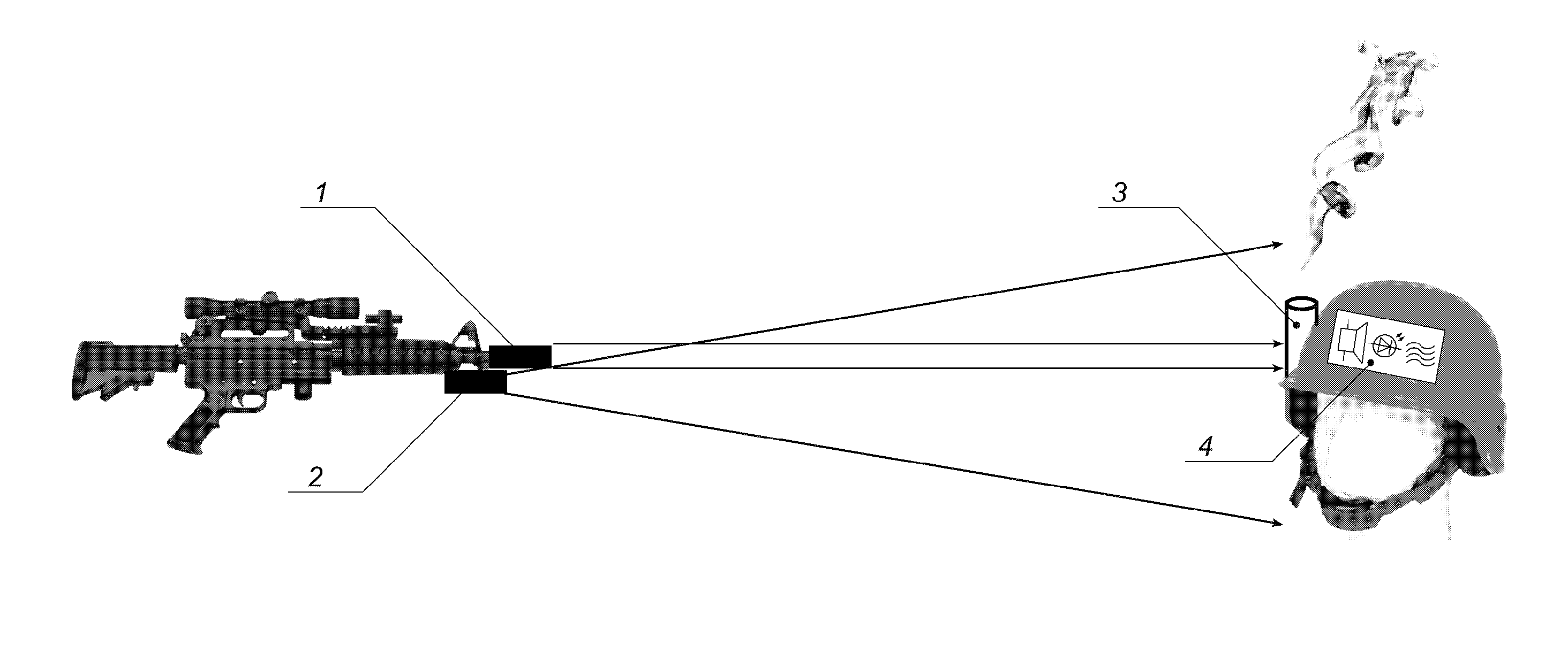
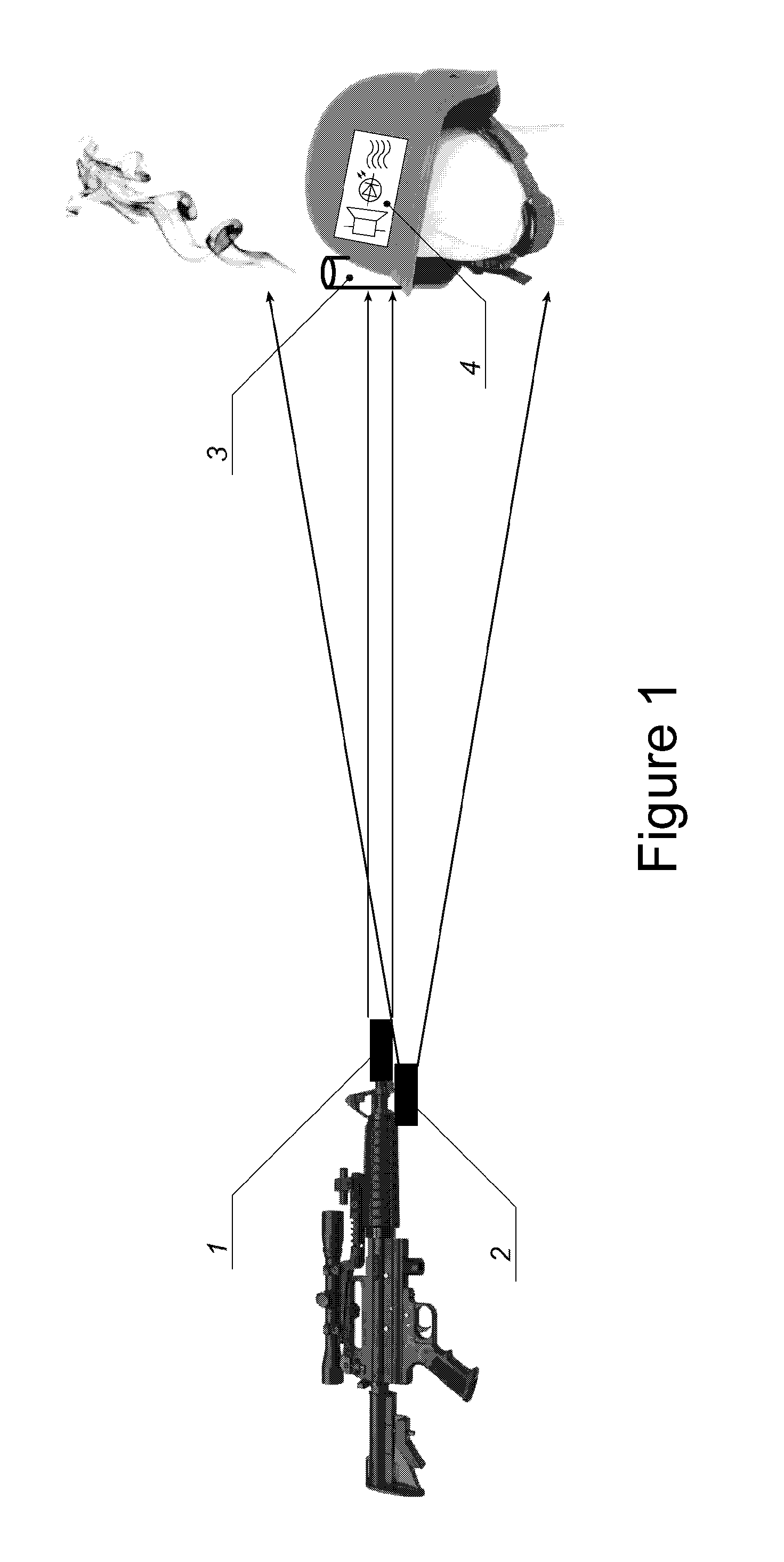
[0019]The extreme optical shooting simulator (FIG. 1) comprises a simulation gun and a personal target, and the personal target has the form of a helmet, a vest or both. Photo sensors are mounted on the surface of the personal target, and electronics for hit processing and devices for realization of the hit effects are integrated in a special housing.

[0020]Two emitters are mounted in the simulation gun—emitter 1 having a narrow beam (i.e. low divergence) with a laser or non-laser light-emitting diode as a source mounted therein; and emitter 2 having a wide beam (high divergence).

[0021]Several (for example, three) “ammunitions” for creating an acoustic pyro effect with smoke 3 and devices for acoustic simulation of flying bullets, a light-emitting diode indication and mechanical vibration 4 are mounted at the personal target.

[0022]Both emitters can emit simultaneously a different code, for example, a tone code over a carrier signal (referred to as a first case in the text below), or ...


PUM


Abstract

The extreme optical shooting simulator is used for team military games and sport competitions and as a tactical training device. It consists of a simulation ‘gun’ and a personal target. Two emitters are mounted on the simulation ‘gun’: a narrow-beam emitter (1) in which a laser or non-laser light-emitting diode is installed as a source; and a wide-beam emitter (2) having a non-laser light-emitting diode installed therein. When a signal is received from the low-divergence emitter (1), a precise hit on the personal target is simulated by means of ‘ammunition’ mounted thereon for an acoustic pyro effect with smoke (3). If a signal is received from the high-divergence emitter (2), devices (4) for the acoustic simulation of flying bullets, a light-emitting diode display and mechanical vibration are activated. The purpose of the invention is to add an extreme hit effect and the effect of bullets flying past the player to optical ‘laser tag’-type shooting simulators.

Description

FIELD OF THE INVENTION[0001]The present invention relates to an extreme optical shooting simulator used for team military games, sport competitions and as a tactical training device.DESCRIPTION OF THE RELATED ART[0002]A “light gun” is known in which the shot is simulated by a non-laser emitter, usually having an infrared light-emitting diode as a source, wherein a personal target for receiving and counting the hits from the simulator which is mounted on the player body comprises a photo-detector array and electronics for hit processing and registration / 1 / . Similar systems have been distributed under the trade name “outdoor laser tag”.[0003]A disadvantage of the “light gun” is the relatively wide beam which is used to simulate a shot, compared to a laser system of this type which makes hitting unrealistically easy. Therefore, it is difficult to be applied as a sport or training means.[0004]Another disadvantage of the “light gun” is the lack of “ammunition” with an extreme effect for...

Claims


Application Information

Patent Timeline
Patent Type & Authority Applications(United States)
IPC IPC(8): F41A33/02
CPCF41J5/24F41A33/02F41A33/04F41G3/2655
Inventor MILANOV, EMIL STEFANOVTINCHEV, VASIL KIRILOV
Owner MILANOV EMIL STEFANOV
Learn More